If you’ve ever searched “wired PIR motion sensor” for an alarm or door-access project, you’ve almost certainly seen two completely different product categories mixed together on the same results page. A PIR (Passive Infrared) motion detector — the kind used in burglar alarm systems — watches for heat-emitting bodies moving through its field of view and signals an alarm panel when it detects one. A Request-to-Exit (RTE) sensor — also often a PIR, same-looking plastic housing — does almost the opposite: it watches for someone approaching a door from the inside so the access-control system can unlock the door and let them leave without touching a button. Same underlying physics, completely different job descriptions, and wiring them wrong causes real problems. This article gives you a structured comparison of both categories, with a close look at the Honeywell IS335 as the benchmark alarm-detection PIR and the RTE PIR category as its access-control counterpart.
What Each Sensor Is Actually Doing
Understanding the functional contract of each sensor type is the fastest way to avoid a costly wiring mistake. The two categories share a technology core but diverge on output type, logic polarity, mounting geometry, and the panel they talk to.
The Alarm-Detection PIR
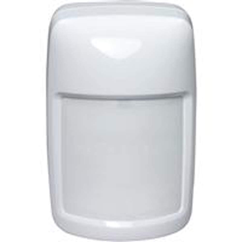
The Honeywell IS335 is a hardwired passive infrared detector rated for indoor commercial and residential use. “Passive” means it emits nothing — it reads ambient infrared (heat) signatures and triggers when a warm body crosses its detection zones. The IS335 outputs a normally-closed (NC) dry contact — the signal loop to your alarm panel stays closed at rest and opens on detection. Nearly every hardwired alarm panel made in the last 30 years — DSC, Bosch, Honeywell/Resideo Vista series, older Brinks and ADT OEM panels — expects exactly this NC loop convention.
Per the Honeywell Security IS335 Passive Infrared Motion Detector Installation Guide, Document 800-05192:
| Parameter | IS335 Value |
|---|---|
| Detection coverage | 90° × 90°, 35 ft. (10.7 m) range |
| Power input | 8.2–16 VDC, ~10 mA quiescent |
| Output | NC dry contact, alarm panel loop |
| Temperature range | 32°F–120°F (0°C–49°C) |
| Tamper output | Yes, separate NC loop |
| Pet immunity | Yes (up to ~40 lbs with correct mount height) |
The IS335’s job is intrusion detection. It is normally armed when the building is unoccupied. The alarm panel supervises the NC loop continuously; a cut wire or sensor removal opens the loop and triggers a tamper condition. This hardwired supervision is the primary reason experienced installers favor wired PIRs over wireless equivalents for commercial installations — there is no battery to die, no RF interference window, and the panel knows instantly if someone physically attacks the sensor.
Request
$39.99
In stock on Amazon
Check price on AmazonThe Request-to-Exit PIR
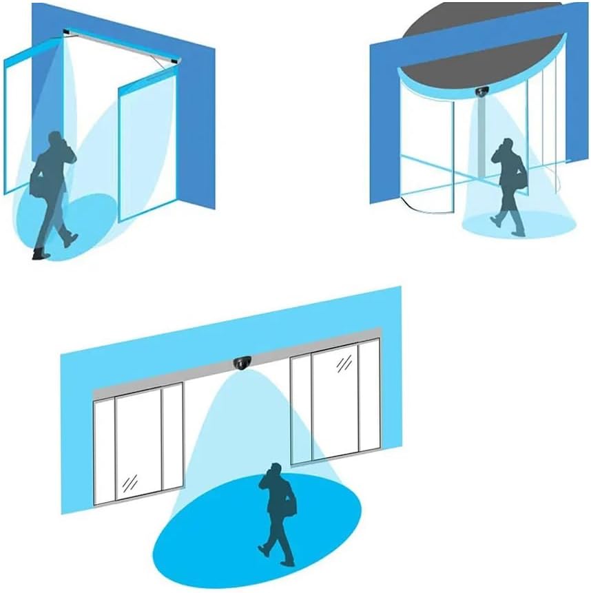
An RTE sensor lives at an access-controlled egress point — typically above a door on the secured side. When someone approaches to leave, the sensor detects them, activates a relay output, and sends a signal to the access-control panel (or directly to an electric strike or magnetic lock) to release the door. This is a life-safety requirement in most jurisdictions under NFPA 101 and IBC egress provisions: occupants must be able to exit without a credential.
The critical differences from an alarm PIR, as documented in HID Global / Lenel Request-to-Exit Sensor Application Notes (HID Global technical documentation):
- Output type: RTE sensors output a relay closure (normally open or normally closed, configurable), not an alarm panel NC supervision loop. The relay actually switches power to the lock or panel input — it carries real load, not just a supervision signal.
- Logic is inverted: An alarm PIR raises an alert on detection. An RTE sensor grants access on detection.
- Always-on orientation: An RTE sensor is active during occupancy, not during vacancy.
- Mounting geometry: RTE sensors are typically ceiling-mounted 8–10 ft. above the door, angled to cover the egress approach zone — not corner-mounted at 7.5 ft. aimed across a room like an alarm PIR.
Because of these differences, wiring an alarm PIR into an RTE application (or vice versa) isn’t just inconvenient — it can leave a door locked against egress or disarm an alarm zone entirely.
IS335
$26.51
In stock on Amazon
Check price on AmazonThe Technology Fork: PIR vs. Microwave RTE
Multiple RTE sensor owners in commercial installation forums report switching from a PIR-based RTE sensor to a microwave radar RTE variant specifically because their PIR unit false-triggered during daylight hours but not at night. This makes physical sense. Passive infrared sensors read contrast between a moving body and the background. During daytime, sunlight streaming through a door sidelight or transom warms background surfaces — a window frame, a painted wall — narrowing the thermal contrast the PIR relies on.
Sensors Magazine’s overview of PIR vs. microwave motion detection technology (sensorsmag.com) identifies this thermal-background sensitivity as the known limitation of PIR in environments with variable radiant heat loads. When thermal contrast collapses, the sensor either fails to trigger (nuisance: door doesn’t unlock) or triggers spuriously on thermal convection currents (nuisance: door unlocks with no one present).
A microwave (K-band or X-band radar) RTE sensor emits a low-power microwave signal and detects the Doppler shift from a moving object. It is not affected by ambient temperature or sunlight. The tradeoff: microwave sensors can detect motion through thin partitions, which occasionally causes nuisance triggers in high-traffic corridors. For most interior door applications where a PIR is experiencing daytime false-triggers, a microwave RTE variant is the correct corrective step — not adjusting sensitivity or repositioning the PIR.
Request
$39.99
In stock on Amazon
Check price on AmazonThe Relay Load Voltage Warning You Need to See
Owners sourcing RTE sensors should read the relay contact ratings carefully before wiring. A well-documented field scenario involves an RTE sensor carrying a relay rating of 60 VAC on its spec sheet, installed in an application requiring switching of a 110 VAC load on the lock power supply. Running a 60 VAC-rated relay contact at 110 VAC risks contact arcing, premature contact failure, and potential fire hazard.
The correct solution is to wire an intermediate relay between the RTE sensor output and the 110 VAC load. The RTE sensor’s relay switches the coil of a properly rated 110 VAC intermediate relay; the intermediate relay’s contacts switch the actual load. Control Engineering’s guidance on relay contact ratings and intermediate relay best practices (controleng.com) documents this as standard practice — not an optional workaround. If your access-control lock power supply runs at 110 VAC and your RTE sensor’s relay is rated below that voltage, an intermediate relay is a code and safety requirement, not a design suggestion.
Automation World’s coverage of access control integration in commercial buildings (automationworld.com) reinforces this point, noting that mismatched relay voltage ratings are among the most common causes of premature lock-control hardware failures in retrofitted access systems.
By the numbers — RTE sensor relay ratings to check before purchasing:
| Scenario | Relay Detail | Action Required |
|---|---|---|
| Lock supply: 12 VDC, RTE relay rated 30 VDC / 1A | Within rating | Wire directly |
| Lock supply: 24 VDC, RTE relay rated 30 VDC / 1A | Within rating | Wire directly |
| Lock supply: 110 VAC, RTE relay rated 60 VAC / 0.5A | Exceeds rating | Intermediate relay required |
| Lock supply: 110 VAC, RTE relay rated 120 VAC / 1A | Within rating | Wire directly |
The Decision Framework: If X, Then Y
Here is the plain decision tree for the common scenarios you’re likely facing:
If you’re replacing a failed sensor on an existing hardwired alarm panel (Vista, DSC, Bosch, Brinks OEM, ADT OEM): Use an alarm-detection PIR like the Honeywell IS335. It wires to your zone terminals as a normally-closed loop, requires no relay, and is documented in the IS335 Installation Guide (Document 800-05192) as compatible with industry-standard supervised zone wiring. Verify your panel’s zone voltage (typically 10–13 VDC) against the IS335’s 8.2–16 VDC input range — it fits virtually every panel in this class.
If you’re adding egress detection at an access-controlled door: Use a dedicated RTE sensor — not an alarm PIR. Check the relay contact rating against your lock power supply voltage before purchasing. If your supply is 110 VAC or if the rated voltage is ambiguous, plan for an intermediate relay in your bill of materials from the start.
If your RTE sensor is false-triggering during daylight hours: Don’t fight the physics. Switch to a microwave radar RTE variant. A PIR in a thermally variable environment near windows or exterior doors will continue to nuisance-trip regardless of sensitivity adjustment. The microwave variant costs roughly the same and eliminates the root cause, as Sensors Magazine’s PIR vs. microwave technology overview documents.
If you need both intrusion detection and egress control at the same door: These are separate panel inputs requiring separate sensors with separate outputs. An alarm PIR feeds the intrusion panel zone; an RTE sensor feeds the access-control panel’s REX input. Some integrated systems accept both on a single controller, but the sensors remain distinct hardware.
Frequently Asked Questions
Will the Honeywell IS335 work as a drop-in replacement for an old Brinks or ADT system?
Yes, in virtually all cases. Brinks and ADT residential and light-commercial panels from the 1990s forward use industry-standard hardwired zone wiring: normally-closed contacts, supervised with end-of-line resistors. The IS335’s NC output and standard four-wire pigtail (power, ground, alarm, tamper) match this convention directly, as detailed in the Honeywell Security IS335 Installation Guide, Document 800-05192. Confirm your panel’s auxiliary power output voltage is within the IS335’s 8.2–16 VDC input range — it almost certainly is.
What is a Request-to-Exit sensor and how is it different from a standard alarm PIR?
An RTE sensor is a motion detector used in access-control systems to detect when an occupant is approaching an exit door from the secured side, allowing the door to unlock without requiring a keycard or PIN. An alarm PIR is used to detect intruders when a building is unoccupied and signals an alarm panel. Both use infrared or microwave motion sensing, but their outputs, panel connections, mounting geometry, and logic are completely different. Using one in place of the other will not work correctly. HID Global / Lenel’s Request-to-Exit Sensor Application Notes provide the access-control panel wiring conventions in detail.
Why does my PIR motion detector false-trigger during the day but not at night?
PIR sensors detect the thermal contrast between a moving body and the background. During daylight, sunlight heats wall surfaces, door frames, and floors, reducing the thermal difference the sensor relies on — a dynamic described in Sensors Magazine’s coverage of PIR vs. microwave detection technology (sensorsmag.com). This can cause spurious triggers from thermal convection or air movement, or it can cause missed detections. At night, background surfaces cool and thermal contrast increases, making the sensor more reliable. If your application is near windows or exterior doors, a microwave radar sensor is the correct technology choice.
Can I switch from a PIR to a microwave radar sensor in an RTE application?
Yes, and in thermally variable environments — particularly near glazing or exterior doors — it is often the right call. Microwave RTE sensors use Doppler radar rather than infrared sensing, making them insensitive to sunlight and ambient temperature changes. The wiring and relay output conventions are typically identical to PIR RTE sensors, so the swap is usually straightforward. Be aware that microwave sensors can detect motion through thin walls or glass, which may require sensitivity adjustment in dense environments.
What load voltage can the RTE sensor’s built-in relay safely switch?
It depends on the specific sensor’s published relay contact rating — check the datasheet, not the product listing title. Many low-cost RTE sensors carry relay ratings of 30 VDC / 1A or 60 VAC / 0.5A. If your lock power supply or panel input runs at 110 VAC or at a current draw exceeding the rated limit, you must use an intermediate relay. The RTE sensor’s relay switches the intermediate relay’s coil; the intermediate relay’s contacts switch the actual load. Control Engineering’s guidance on relay contact ratings and intermediate relay best practices (controleng.com) treats this as a hard electrical limit. Running a relay above its rated voltage risks arcing, contact welding, and fire.