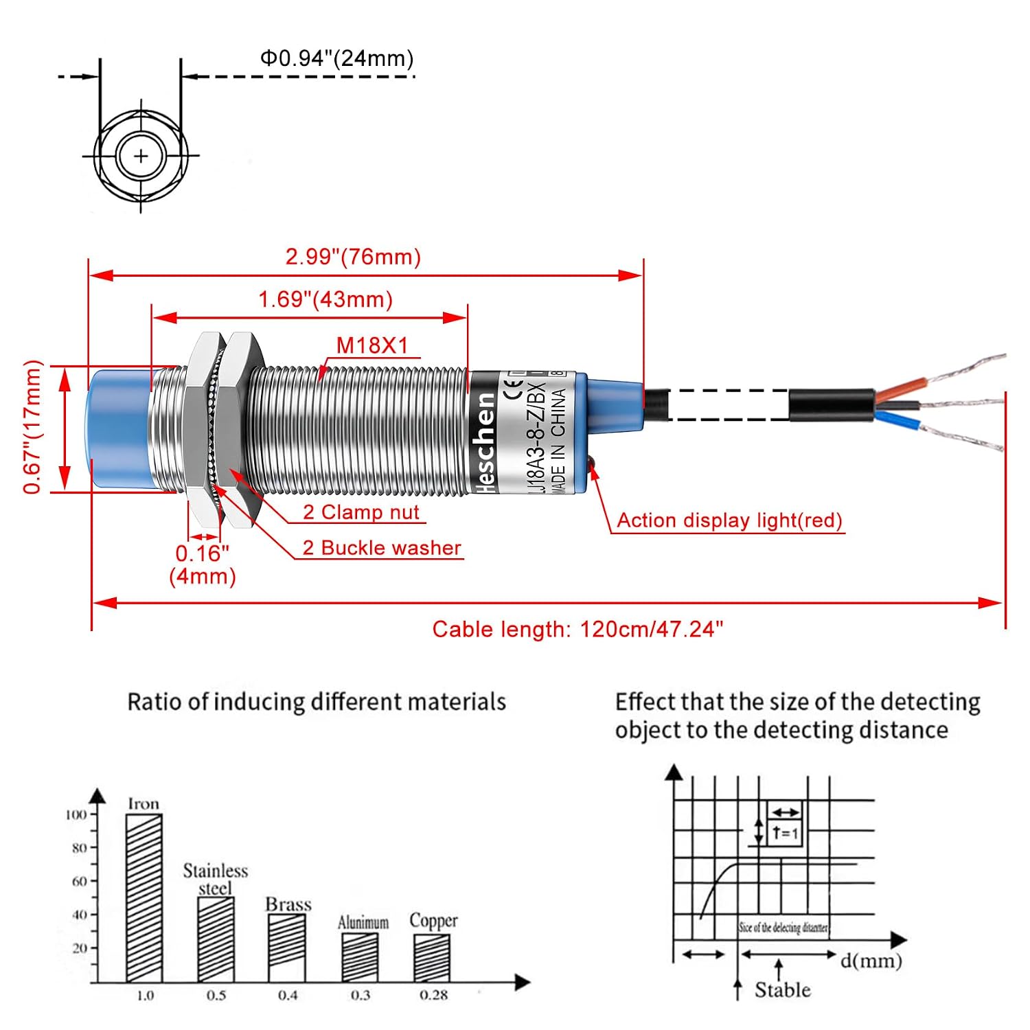
If your first layer of bed leveling ever failed mid-print — the nozzle gouging your build plate while the printer happily continued — you already understand why Z-probe reliability matters. Auto bed leveling (ABL) works by using a sensor, mounted near the hotend, to measure the distance between the nozzle and the print surface at multiple points before each print. The firmware (usually Marlin) then builds a height map and compensates for any warp or tilt in real time. The sensor doing that measuring is almost always either an inductive proximity sensor (detects metal by generating an electromagnetic field) or a capacitive proximity sensor (detects both metal and non-metal by measuring changes in electrical capacitance). Getting that sensor choice wrong — or wiring it incorrectly — is one of the most common causes of first-layer failures, board damage, and, in documented cases, outright bed crashes. This guide cuts through the noise so you can make a confident decision for your specific build surface and printer electronics.
Inductive vs. Capacitive: Choosing Based on Your Build Surface
The fundamental fork in the road is simple: what is your print surface made of?
Inductive sensors work exclusively on electrically conductive materials — steel, aluminum, and (with reduced range) copper and brass. If your printer runs a spring-steel PEI sheet, a standard aluminum heated bed, or a magnetic flex plate with a steel base, an inductive sensor is the more reliable choice. The detection mechanism is immune to surface color, texture, coating thickness (within reason), and ambient humidity. As Sensors Magazine’s overview of proximity sensing technologies notes, inductive sensors offer inherently cleaner switching behavior on ferrous targets because the electromagnetic interaction is strong and consistent.
Capacitive sensors, by contrast, can detect virtually any material — glass, PEI film bonded to a non-steel carrier, wood, ceramic, and even water. That versatility comes with a tradeoff: sensitivity to everything means sensitivity to the wrong things too. Humidity gradients, loose filament strands on the bed surface, and even air turbulence from part-cooling fans have all been documented in aggregated owner reviews as false-trigger sources. More on that setup friction in the FAQ section below.
By the numbers — typical detection range vs. usable range on common build surfaces:
| Sensor Type | Rated Sensing Distance | Practical Range on Ferrous Steel | Practical Range on Glass/PEI | Practical Range on Aluminum |
|---|---|---|---|---|
| Inductive (standard) | 4 mm | ~3.5–4 mm | Not applicable | ~2–2.5 mm |
| Inductive (ferrite-core) | 8 mm | ~7–8 mm | Not applicable | ~4–5 mm |
| Capacitive (standard) | 4–8 mm | ~4–6 mm | ~3–5 mm | ~3–5 mm |
That aluminum column deserves immediate attention. Inductive sensors are rated for ferrous (iron-based) targets. On non-ferrous conductive materials like aluminum — the most common heated bed substrate — the actual usable sensing distance is roughly 50–60% of the rated value. A sensor marketed as “4 mm sensing distance” may only reliably trigger at 2 mm on your aluminum bed. This is not a defect; it is physics. Control Engineering’s application matching guide confirms this derating factor and recommends specifying sensors against the actual target material, not the rated ferrous-steel distance. This is the single most important buying warning in this category, and it is why sensors that seem to work fine during bench testing can fail on a real printer with a non-ferrous surface.
⚠ Critical Callout: The 4 mm Sensor / 2 mm Reality on Non-Ferrous Surfaces
If your rated sensing distance is 4 mm and your target is aluminum (not steel), your reliable detection distance drops to approximately 2 mm or less. Mount your sensor accordingly — or choose a longer-range sensor rated for non-ferrous targets. Owners who set their sensor mount height based on the label spec and then wonder why the sensor won’t trigger (or triggers inconsistently) are nearly always running into this derating. There is no firmware fix. Adjust the mount height or change the sensor.
Voltage Compatibility and Level Shifting: Protecting Your Mainboard
This is where most wiring mistakes happen, and a single wiring error can destroy a mainboard.
Most proximity sensors in the 3D printer market are designed to operate on 6–36V supply voltage (the industrial standard). Most 3D printer mainboards — including the Creality boards used in the Ender 3 family and many SKR variants — expose a 5V probe input for the Z-probe signal line. If you connect a 24V-powered sensor’s output signal directly to a 5V logic input, you will likely damage or destroy the input protection diode on the mainboard. Documented owner reviews include at least one confirmed board failure from this exact mistake.
The correct approach depends on your printer’s supply voltage:
Scenario 1: 12V printer, inductive sensor rated 6–36V (NPN output) A 12V-powered sensor with NPN open-collector output can be connected to a 5V logic input through a simple resistor-based voltage divider. One reviewed build documents the specific resistor divider as a 4.7 kΩ resistor from the signal line to ground and a 10 kΩ resistor from the signal line to the 5V input, creating a divided voltage that stays within safe logic thresholds. This is a standard level-shifting technique described in Machine Design’s proximity sensor application notes.
Scenario 2: 24V printer (Ender 3 Pro, most Creality v4.x boards), inductive sensor rated 6–36V At 24V, a resistor divider alone is insufficient — the voltage drop across a simple divider won’t reliably protect a 5V input, and signal integrity suffers. The clean solution is a dedicated logic-level converter module (a bidirectional level shifter, available as a four-channel breakout board). These modules use MOSFETs to translate signal levels cleanly and are the approach recommended in Marlin’s own Z probe configuration documentation. Alternatively, some sensors are now sold with integrated 5V-compatible output variants specifically for 3D printer use — verify the output signal voltage on the datasheet, not just the supply voltage range.
The leaked-voltage failure mode: At least one documented owner review describes a bed crash caused by a sensor that did not switch cleanly to 0V when untriggered — it “leaked” a residual voltage above the logic threshold, causing the mainboard to see a permanent trigger state. The printer therefore thought the probe was always detecting the bed and refused to move downward, then crashed when the signal behavior changed unpredictably at temperature. This is a real failure mode, not an edge case. Always verify open-circuit output voltage (should be 0V for NPN off-state, supply voltage for PNP off-state) before trusting a sensor with critical motion.
NPN vs. PNP Output, and What Marlin Actually Expects
NPN (sinking) output: The sensor’s output pin pulls to GND when triggered. Most 3D printer probe inputs are designed for NPN sensors — they have a pull-up resistor to 5V internally, so the probe reads HIGH (untriggered) and LOW (triggered). This is the default assumption in Marlin’s Z-probe configuration.
PNP (sourcing) output: The sensor’s output pin pulls to the supply voltage when triggered. A PNP sensor connected directly to a Marlin-configured NPN input will read as always-triggered (because the pin is being pulled high even when the sensor hasn’t detected anything). You can use a PNP sensor by inverting the probe logic in Marlin — specifically, by setting Z_MIN_PROBE_ENDSTOP_INVERTING to true — but you also need to ensure the output voltage doesn’t exceed the input’s logic level (back to the level-shifting problem).
Machine Design’s output-type comparison guide recommends defaulting to NPN for 3D printer applications unless you have a specific reason for PNP, simply because NPN is what the ecosystem assumes. Banner Engineering’s proximity sensor application guide echoes this for automation contexts where the controller’s input type may be fixed.
For Marlin configuration, the relevant settings are in Configuration.h:
#define Z_MIN_PROBE_PIN— assigns the probe to the correct physical pin#define Z_MIN_PROBE_ENDSTOP_INVERTING— settruefor PNP,falsefor NPN#define NOZZLE_TO_PROBE_OFFSET— the X, Y, and Z offset of the sensor mount relative to the nozzle
The probe Z offset is the distance from the sensor’s trigger point to the nozzle tip. If the sensor triggers at 2 mm above the bed and the nozzle is 2.5 mm lower than the sensor body’s centerline, your Z offset is negative (e.g., -2.5). This must be measured physically and entered accurately — no amount of firmware tuning compensates for a wrong offset value.
Versatility Note: Where These Sensors Show Up Beyond Printers
Before the FAQ, it is worth briefly acknowledging that the sensors covered here have a much wider footprint than 3D printing. Aggregated buyer reviews for the same sensor SKUs include use cases as specific as brass primer detection in reloading presses, grain-flow sensing in agricultural equipment, and reverse-light triggering in Can-Am X3 side-by-side vehicles (where the sensor detects the presence of a metal component to activate lighting). These aren’t hobbyist edge cases — they reflect the industrial lineage of these components. A sensor that passes muster for a reloading press (where a miss means a destroyed case or worse) carries meaningful real-world validation that no 3D printer benchmark fully replicates.
Frequently Asked Questions
1. Will an inductive proximity sensor work with a glass, PEI film, or removable non-metal build plate?
No — not reliably, and in most configurations, not at all. Inductive sensors require a conductive target. If your build surface is glass, PEI film on a non-steel carrier, or any other non-conductive material, you need a capacitive sensor or a different probing solution (BLTouch/CR Touch use a physical pin and work on any surface). If your PEI sheet sits on a steel spring-steel base, the inductive sensor can detect the steel through the PEI layer, provided the PEI thickness doesn’t push the sensor beyond its usable range.
2. My Ender 3 runs 24V — how do I safely connect a proximity sensor to the 5V probe input without damaging the mainboard?
Use a dedicated MOSFET-based bidirectional logic-level converter between the sensor’s output pin and the mainboard’s probe input. Do not use a simple resistor divider at 24V — the math doesn’t safely land within 5V tolerances. Some sensor variants are sold with 5V output signal lines at 24V supply; verify the output spec on the datasheet explicitly. Marlin’s Z probe documentation specifically addresses this wiring concern for common Creality boards.
3. Why does my new capacitive proximity sensor appear to be always-on (triggered) right out of the box?
The sensitivity adjustment potentiometer (a small screw on the sensor body) is almost certainly set too high from the factory. This is a documented pattern across multiple owner reviews for capacitive sensors in this class. Turn the adjustment screw counterclockwise — often many full rotations — until the indicator LED extinguishes with no target present. Then slowly increase sensitivity until the sensor reliably detects your build surface at the intended mount distance. This is normal setup behavior, not a defect.
4. What is the actual reliable detection distance for a 4mm-rated sensor on a non-ferrous or non-metal surface?
On aluminum (non-ferrous conductive), expect approximately 2 mm of reliable detection distance from a 4 mm-rated sensor — roughly 50% of the rated spec. On glass or PEI (non-conductive), an inductive sensor will not trigger at any distance; use a capacitive sensor rated for the specific target material. Always size your sensor mount height based on the derated value, not the label spec.
5. Should I use NPN or PNP output for my 3D printer, and does it matter for Marlin firmware?
Default to NPN. Most 3D printer mainboards expect NPN (sinking) output, and Marlin’s default probe configuration is written for NPN. PNP sensors can work but require inverting the probe logic in Configuration.h and careful attention to output voltage levels. If you already have a PNP sensor, it is usable — just set Z_MIN_PROBE_ENDSTOP_INVERTING true and verify the signal voltage is within the mainboard’s 5V logic range.
6. How do I configure Marlin to use a proximity sensor as a Z-probe, and what is the probe offset?
In Configuration.h, enable Z_MIN_PROBE_ENDSTOP, set the appropriate pin, and configure the invert flag per your sensor’s output type. The probe offset (NOZZLE_TO_PROBE_OFFSET) requires three values: X and Y distance from the nozzle to the sensor centerline (measured physically on your mount), and the Z offset — the distance from the sensor’s actual trigger point (not the sensor body bottom) to the nozzle tip when the trigger fires. Measure the Z offset empirically: home Z with the sensor, then use PROBE_CALIBRATE or paper-test the nozzle height manually and calculate the difference. A 48-point repeatability test documented in owner field notes showed a standard deviation of 0.005 mm for a well-mounted, correctly wired inductive sensor — achievable, but only after the offset is dialed in precisely and the mount has no mechanical play.
Decision rule: If your build surface has a steel or iron base (spring steel, PEI on steel, standard magnetic flex plate), use an inductive sensor with an 8 mm rated range to give yourself adequate working margin after derating. If your surface is aluminum, glass, bare PEI film, or anything non-ferrous, use a capacitive sensor and plan for a multi-turn calibration at first setup. In either case, resolve your voltage compatibility before powering up — a level-shifter module costs less than a mainboard.