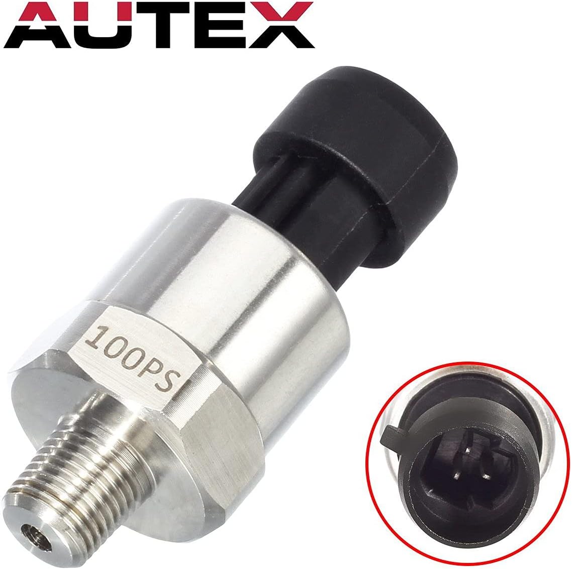
A pressure transducer is a small device that converts fluid or gas pressure into an electrical signal your gauge, controller, or ECU (engine control unit — the brain of a fuel-injected engine) can read. Most people encounter them first in an automotive context, bolted to a fuel rail or oil galley. But the underlying sensor — a piezoresistive (pressure-sensitive resistor) element sealed inside a stainless steel body with an NPT (National Pipe Thread, the standard US pipe fitting) port — doesn’t care whether it’s measuring fuel pressure or well-water pressure. That indifference has quietly built an unusually broad user base around a class of sensors originally designed to replace AEM aftermarket gauges. If you’re deciding right now whether one of these sub-$30 units belongs in your irrigation controller, submersible pump system, or industrial sprayer, this guide walks you through the tradeoffs that matter — signal type, pressure range, materials, and the QC risks you should price into your decision.
| EDITOR'S PICK[AUTEX 100psi Pressure Transduce…](https://www.amazon.com/dp/B00NIK9E10?tag=greenflower20-20) | Mid-tier[AUTEX 200 Psi Pressure Transduc…](https://www.amazon.com/dp/B00NIK900K?tag=greenflower20-20) | Budget pick[Hoypeyfiy 3pcs 45RFE 545RFE 68R…](https://www.amazon.com/dp/B01MYBHPUX?tag=greenflower20-20) | |
|---|---|---|---|
| Pressure range | 100 psi | 200 psi | — |
| Thread size | 1/8"-27 NPT | 1/8"-27 NPT | — |
| Material | 316 Stainless Steel | Stainless Steel | — |
| Connector harness | ✓ | ✓ | — |
| Compatibility | Oil, Fuel, Air, Water | Oil, Fuel, Air, Water, Diesel, Gas | 45RFE, 545RFE, 68RFE |
| Price | $41.99 | $29.99 | $21.59 |
| See on Amazon → | See on Amazon → | See on Amazon → |
Why These Units Have Escaped the Fuel Rail
The AEM replacement use case is the single most documented thread across aggregated Amazon reviews for this sensor category: owners consistently report that all-stainless aftermarket transducers outlast the original brass-and-plastic AEM sensors, often by a significant margin. That reliability reputation — plus a 1/8-inch NPT port that threads into a staggering number of existing fittings — is what pushed these sensors into completely different applications.
The pattern is straightforward:
- A water well installer realizes that a 0–100 PSI transducer rated for continuous immersion in petroleum products is almost certainly rated for continuous immersion in water.
- An irrigation technician with an ESP Home (open-source home-automation firmware) setup wants analog pressure feedback without paying industrial-sensor prices.
- A Graco airless paint-sprayer owner chases an over-pressurization fault that’s been dumping paint out the drain hose — and discovers the OEM transducer has drifted out of calibration.
Each of these buyers lands on the same $15–$30 stainless unit because the specs fit, the thread fits, and the signal output (usually 0–5 V or 4–20 mA) fits what they already have.
Matching Pressure Range to Application
Getting the pressure range wrong is the fastest way to either destroy a transducer or get useless data. Here’s the practical mapping:
| Application | Typical Operating Pressure | Recommended Range | Notes |
|---|---|---|---|
| Residential water well (pump output) | 40–80 PSI | 0–100 PSI | Provides good resolution across normal duty cycle |
| Irrigation district supply line | 60–120 PSI | 0–150 PSI | Accounts for surge events |
| AEM / EFI fuel pressure replacement | 0–100 PSI (NA), 0–150 PSI (FI boost) | Match to system max | Rotary engine compression testing is a special case — see below |
| Graco airless paint sprayer | 0–3,300 PSI (tip) but transducer port is pre-pump | 0–300 PSI typical | Verify OEM spec before ordering |
| Hydraulic / industrial process | Application-specific | Over-range by 2× minimum | Budget stainless units are not rated for hydraulic shock |
A note on the Mazda rotary compression-tester use case: One owner used a 200 PSI variant as a replacement compression tester (the standard rotary engine cylinder check port accepts 1/8-inch NPT). This is a dynamic, pulse-type measurement — not continuous-duty — so the transducer sees brief spikes to 150–180 PSI on a healthy engine. The 200 PSI unit has adequate headroom; a 100 PSI unit does not. Per published specs on piezoresistive sensors (Sensors Magazine, “Piezoresistive Pressure Sensor Fundamentals”), exceeding 150% of rated pressure risks permanent zero-shift in the sensing element — meaning the transducer reads low forever after, with no visible damage signal.
Signal Type: 0–5 V vs. 4–20 mA — Show the Math
This is the decision that trips up more buyers than the pressure range, and it’s worth being explicit about the tradeoff.
0–5 V (ratiometric voltage output):
- Simple. Three wires: power, ground, signal. The signal pin swings from 0 V at zero pressure to 5 V at full-scale pressure (e.g., 100 PSI).
- Ideal for: ECUs, standalone gauge clusters, microcontrollers (Arduino, ESP Home), AEM gauges.
- Weakness: voltage signals are susceptible to noise over long cable runs. Beyond roughly 3–5 meters, you may see jitter, especially near ignition systems or VFDs (variable-frequency drives — motor controllers that generate significant electrical noise).
4–20 mA (current loop):
- The signal is a current rather than a voltage. 4 mA = zero pressure; 20 mA = full-scale. Because current is constant through the loop regardless of wire resistance, this signal travels cleanly over 100+ meter runs without degradation.
- Ideal for: PLCs (programmable logic controllers), SCADA systems, building automation inputs, irrigation controllers with 4–20 mA analog card slots.
- Weakness: requires a load resistor (typically 250 Ω for a 1–5 V input) if your controller expects voltage. Adds a small calculation step.
The math for a 0–100 PSI / 4–20 mA unit:
Signal span = 20 mA − 4 mA = 16 mA Pressure span = 100 PSI − 0 PSI = 100 PSI Scale factor = 100 PSI / 16 mA = 6.25 PSI/mA Measured current = 12 mA → Pressure = (12 − 4) × 6.25 = 50 PSI
Per Control Engineering’s guidance on selecting pressure transmitters, the 4–20 mA standard persists in industrial settings precisely because it’s immune to ground loops and voltage drop — factors that matter enormously when your transducer is 80 feet from your control panel at the wellhead.
Per Machine Design’s comparison of signal types, 0–5 V wins on simplicity and cost when cable runs are short and electrical noise is low; 4–20 mA wins on everything else at longer distances.
Decision rule: If your receiver is a microcontroller within 5 meters, buy the 0–5 V unit. If your receiver is a PLC, a distributed I/O card, or anything at the end of a conduit run, buy the 4–20 mA unit.
The Graco Airless Sprayer Case — and What It Reveals About False Readings
The GDHXW transducer’s documented resolution of an over-pressurization fault in a Graco airless sprayer is worth unpacking because it illustrates a broader diagnostic principle.
The owner’s original diagnosis was a valve problem — the sprayer was dumping paint out the drain hose, which is consistent with a stuck pressure-relief valve. But the actual root cause was a transducer that had drifted: it was reporting lower pressure than actual, so the sprayer’s control circuit kept commanding the pump to build more pressure, eventually tripping the mechanical relief. Replacing the transducer corrected the reading, the control loop normalized, and the fault disappeared.
This matters for you if you’re in any closed-loop pressure control system — well pump pressure switches, irrigation zone controllers, sprayer pressure regulators — because a failed transducer rarely announces itself with a dead output. More commonly it drifts: the zero shifts, the span compresses, or it becomes intermittently noisy. The 1-star review pattern on budget 100 PSI units documents exactly this: false readings that don’t fail obviously, they just erode system performance invisibly until something downstream breaks.
What causes false or erratic readings in these transducers?
- Moisture intrusion at the connector (most common on budget units without IP67-rated connectors)
- Overpressure event that permanently shifted the sensing element
- Electrical noise coupling into a long 0–5 V cable run
- Wiring error — specifically, reversed power and signal pins, which can damage the internal amplifier circuit without killing the sensor entirely
- QC variation in budget tiers, where thin stainless diaphragms may have inconsistent welding at the pressure port
For continuous-duty installations — wells, irrigation systems, process monitoring — it’s worth spending the extra $8–$12 on a unit with a documented IP67 rating and locking connector rather than a bare flying-lead wire harness.
How Long Do They Last? Owner Data vs. Rated Specs
Based on aggregated owner reviews, the durability picture for continuously-installed stainless units is genuinely encouraging:
- One owner ran an AUTEX 100 PSI unit for 2.5 years continuously monitoring a residential well without recalibration or failure.
- Multiple irrigation-system owners report 12–24 months of outdoor, weathered service.
- AEM replacement users report outlasting the OEM sensor lifespan, though automotive thermal cycling is a different stress profile than static water pressure.
The ISA’s process instrumentation terminology standard (ISA-51.1) defines useful life for wetted pressure sensors as a function of overpressure cycles, temperature range, and media compatibility. For water and light petroleum at temperatures below 85°C, a welded stainless sensing element is the correct material choice. Budget units that use brass ports with a stainless diaphragm insert are a hybrid — fine for fuel and water, problematic for chlorinated irrigation water at higher concentrations or for any ammonia-bearing fluid.
By the numbers:
- 0.5% full-scale accuracy: typical spec for budget stainless units
- IP67: minimum protection rating for outdoor or splash-exposure installs
- 1/8-inch NPT: universal thread on this product category; fits AEM gauge fittings, Graco port adapters, and standard plumbing fittings directly
- $15–$30: current May 2026 price range for single units across the major distributors
Frequently Asked Questions
Will a 1/8-inch NPT pressure transducer thread directly into an AEM gauge fitting without an adapter?
Yes. AEM’s fuel pressure gauge sender port is a 1/8-inch NPT female fitting, and the transducers in this category ship with a 1/8-inch NPT male port. This is a direct thread engagement — no adapter required. Use PTFE (Teflon) thread tape, two to three wraps, and torque to 15–20 ft-lb. Do not over-torque into aluminum fittings; the NPT taper will crack the boss.
What output signal type do I need — 0–5 V or 4–20 mA — for my ECU or gauge?
Most aftermarket ECUs (Megasquirt, Haltech, AEM Infinity) and standalone gauge clusters expect a 0–5 V ratiometric signal. If your device’s wiring diagram specifies a sensor supply voltage of 5 V and a signal input pin, buy the 0–5 V variant. If your device has a dedicated 4–20 mA analog input (common on PLCs and industrial controllers), buy the current-loop variant. When in doubt, check your device’s sensor input specification — it will list the expected signal type explicitly.
Can a 0–100 PSI transducer be used for water well level monitoring, and how do I convert PSI to feet of water?
Yes, with one important caveat: you’re measuring pump output pressure, not static water column depth, unless the transducer is submerged at the bottom of the well. For pump-output monitoring, a 0–100 PSI unit is appropriate for residential systems (40–80 PSI range). For depth-to-water calculation from a submerged unit: 1 PSI = 2.31 feet of fresh water. A reading of 43.3 PSI from a submerged transducer means the sensor is under 100 feet of water column. Submersion requires a transducer rated for full immersion (IP68 or hermetically sealed) — a standard IP67 connector is not adequate for continuous submersion.
How long do these budget stainless steel transducers last in continuous-duty installations?
Based on aggregated owner reviews, 2–3 years of continuous service is well-documented for name-brand budget units (AUTEX, GDHXW) in water and fuel applications. Failure modes at end-of-life are typically drift rather than hard failure. For critical systems, plan a functional verification check (compare reading against a known-good gauge) at 18-month intervals.
Is a non-OEM Graco pressure transducer safe to use in an airless paint sprayer?
Mechanically, yes — if the replacement unit is rated for the operating pressure of your specific sprayer model and uses compatible wetted materials (stainless steel for most water-based and solvent-based coatings). The safety risk is calibration drift: if the replacement transducer reads low, your sprayer’s control circuit will over-pressurize the system, potentially triggering the mechanical relief. Verify the replacement’s output curve against a reference gauge before returning the sprayer to service.
What causes a pressure transducer to give false or erratic readings?
The most common causes, in rough order of frequency based on owner review patterns: moisture intrusion at the connector, overpressure damage to the sensing diaphragm, electrical noise on the signal wire (especially near ignition systems or VFDs), wiring errors on initial installation, and manufacturing QC variation in the sensing element. A transducer that reads fine at zero pressure but drifts at mid-scale usually has overpressure damage. A transducer that reads correctly in isolation but jitters in the installed system usually has a noise or grounding problem. A transducer that reads zero under pressure has usually had its signal and power pins reversed.
The Decision Framework
If your application is short cable run, ECU or microcontroller receiver, automotive or motorsport: buy the 0–5 V stainless unit in the range that gives you 150% headroom over your expected maximum pressure.
If your application is long cable run, PLC or industrial controller, outdoor or wet environment: buy the 4–20 mA unit with a documented IP67 or better connector rating. Spend the extra margin on the connector, not on brand name.
If your application is continuous-duty water or well monitoring: budget stainless units have earned the track record at this point. Buy a second unit as a spare, verify the output against a known reference gauge on installation, and check calibration at 18 months.
If your application is a closed-loop pressure control system (sprayer, pump controller, process regulator): treat the transducer as a consumable with a defined inspection interval. A drifted transducer in a control loop causes downstream damage that costs far more than the sensor itself.