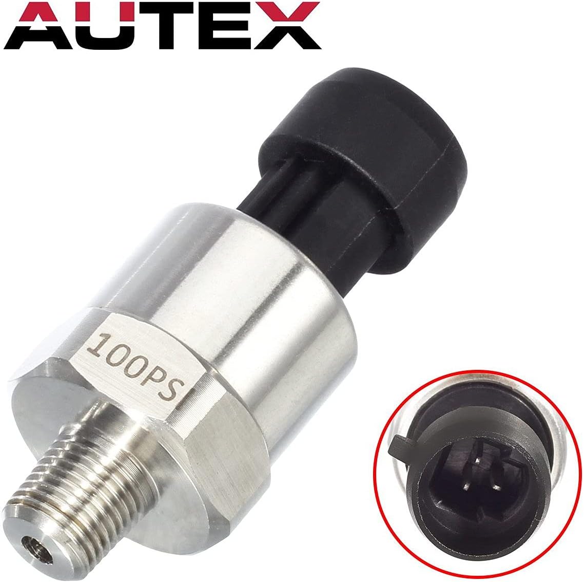
A pressure transducer is a device that converts fluid pressure — the force a liquid or gas exerts on the walls of a pipe or vessel — into an electrical signal your controller, PLC, or data logger can read and act on. If you’re sizing a hydraulic power unit, monitoring fuel rail pressure on a test stand, or building a water distribution skid, getting this selection wrong doesn’t just mean buying twice: it can mean a failed certification, a slow leak at a mismatched thread, or a sensor that rails at the high end and gives your control system garbage data. This guide covers the three decisions that trip up practitioners most often — NPT thread size and compatibility, output signal type, and PSI range selection — with enough math and hard tradeoff framing to turn a pending spec into a confident purchase order.
NPT Thread: Why “Close Enough” Is a Leak Waiting to Happen
NPT stands for National Pipe Taper — a thread standard where the thread diameter tapers along its length so that when you wrench fittings together, the taper creates the seal. It is not a face-seal connection; the seal forms in the thread engagement itself, usually with PTFE tape or anaerobic thread sealant as a secondary barrier.
The two thread sizes you’ll encounter on almost every transducer in the $50–$600 range are 1/4″ NPT and 1/8″ NPT, with 1/2″ NPT showing up on higher-flow industrial manifold blocks. The critical mistake practitioners make at this stage is confusing NPT with BSPT (British Standard Pipe Taper), which looks nearly identical on casual inspection but has a different thread angle (55° vs. 60°) and will cross-thread or leak under pressure. If your manifold is BSPT (common on imported hydraulic power units), you need either a BSPT-native transducer or an adapter rated for your system pressure — not a pipe wrench and optimism.
Torque matters more than you think. Omega Engineering’s pressure transducer selection guide explicitly warns against over-torquing NPT transducers: the tapered thread design means additional turns past hand-tight plus 1–2 wrench turns can crack the sensor body or distort the sensing element, especially on brass-bodied units rated below 1,000 PSI. Spec sheets from Honeywell’s MLH Series and Balluff’s BSP pressure sensor series both specify torque limits between 15–25 ft-lb depending on body material. If you’re torquing by feel on a production floor, you’re gambling.
Quick compatibility check before you buy:
| Port | Thread angle | Sealing method | Common on |
|---|---|---|---|
| 1/4″ NPT | 60° | Taper + sealant | US hydraulics, water skids, HVAC |
| 1/8″ NPT | 60° | Taper + sealant | Fuel rail, pneumatics, small manifolds |
| 1/4″ BSPT | 55° | Taper + sealant | Imported pumps, European OEM |
| 1/4″ BSPP | 55° | Face/O-ring | European, requires flat-face port |
Confirm your manifold standard before you write the PO. A distributor like Digi-Key or AutomationDirect will list the port type in the parametric filter — use it.
Output Signal: Matching Your Transducer to Your Controller Architecture
This is where most mid-career practitioners burn time second-guessing themselves, because the “right” answer is almost entirely dictated by what’s already in your panel — not by any inherent superiority of one signal type over another.
4–20 mA (Current Loop)
This is the dominant industrial standard for a reason: current signals are inherently immune to resistive voltage drop over long cable runs. Per Sensors Magazine’s coverage of pressure sensor output options, a 4–20 mA signal can travel 1,000 feet of 22 AWG wire with no signal degradation, whereas a 0–5 V or 0–10 V output will lose fidelity as wire resistance increases. The “live zero” at 4 mA also lets your controller distinguish between a powered sensor reading zero pressure and a broken wire — a diagnostic advantage that’s saved many a midnight troubleshooting session.
The tradeoff: you need a loop-powered supply (typically 24 VDC, sometimes 12–36 VDC range) and an analog input card that accepts current. If your PLC’s analog cards are voltage-input only, you’re adding a burden resistor (usually 250 Ω for a 1–5 V drop) or an inline converter, both of which are solvable but add BOM line items.
0–5 V and 0–10 V (Voltage Output)
These dominate in short-run OEM applications — engine test stands, small data acquisition systems, benchtop rigs — where cable runs are under 20 feet and the controller’s input impedance is high enough not to load down the signal. Voltage outputs are simpler to wire and debug with a multimeter. Automation World’s coverage of industrial pressure sensor selection notes that voltage-output transducers are common in mobile equipment and automotive testing where 12 VDC supply rails are already present and cable runs are short by definition.
The tradeoff: ground loops. If your sensor and your controller don’t share a clean common ground, you’ll see offset errors. In multi-sensor installations this becomes a real engineering problem, not a theoretical one.
Ratiometric (0.5–4.5 V)
If you’re designing a system where supply voltage can vary — say, a mobile hydraulic application running off a generator — a ratiometric output scales proportionally to the supply voltage, keeping your signal-to-supply relationship constant. This is common in automotive and off-highway OEM designs. The downside: your DAQ or controller needs to reference the same supply, which complicates multi-board designs.
Digital (IO-Link, CAN, Modbus)
IO-Link is the rising star here for factory automation. Balluff’s BSP series and similar offerings from Balluff and Sick allow parametric reconfiguration over the same two-wire data connection — you can change measurement range, output behavior, or alarm thresholds without touching the sensor physically. For installations where sensors live inside a guarded machine enclosure, this is a legitimate time-saver. The tradeoff is IO-Link master cost and the fact that your controls architect needs to have planned for it.
The decision rule is blunt: If your control panel already has 4–20 mA analog input cards and runs are over 20 feet, specify 4–20 mA and don’t overthink it. If you’re building a bench-test OEM rig with a DAQ card and sub-10-foot cables, 0–5 V or 0–10 V is simpler. If you’re specifying a new machine for a sophisticated customer, price IO-Link and let the integration cost make the argument.
PSI Range Selection: Why Overspecifying Costs You More Than Money
Getting the PSI range right is a straightforward-seeming problem that has a non-obvious failure mode: over-ranging is almost as bad as under-ranging, not because the sensor blows up, but because you lose resolution where you need it.
Most transducers output their full signal span across the rated measurement range. A 0–5,000 PSI sensor running on a hydraulic circuit that normally operates between 1,500–2,500 PSI is using roughly 20% of its output span for normal operation. If your controller has a 12-bit ADC (4,096 counts), you now have roughly 820 counts representing your operating band. That sounds like plenty until you’re trying to resolve a 10 PSI pressure drop across a filter to diagnose a clogging condition — at that scale, you want every bit of resolution you can get.
The Math
By the numbers:
- 12-bit ADC = 4,096 counts total
- 0–5,000 PSI sensor on a 1,500–2,500 PSI circuit = ~820 counts of operating resolution
- 0–3,000 PSI sensor on the same circuit = ~1,365 counts of operating resolution (+66% improvement)
- Resolution per count: 5,000 PSI / 4,096 ≈ 1.22 PSI/count vs. 3,000 PSI / 4,096 ≈ 0.73 PSI/count
Omega Engineering’s selection guide recommends sizing the transducer range so that normal operating pressure falls between 50–80% of full scale. This gives you headroom for pressure spikes (water hammer, pump startup transients) without sacrificing resolution during steady-state monitoring.
Media Compatibility Is a PSI Range Conversation Too
For oil and fuel service, confirm the wetted-materials spec — 316L stainless steel sensing diaphragms are the standard for petroleum-based fluids. For water service (especially potable), look for NSF/ANSI 61 compliance if the sensor contacts drinking water. For fuel systems, confirm compatibility with the specific fuel: biodiesel blends (B20, B100) attack certain elastomers, and ethanol-blended fuels (E85) have different dielectric properties than pure gasoline. ISA’s instrumentation standards library is a useful starting reference for media compatibility by application.
A frequently missed detail: burst pressure vs. proof pressure. Proof pressure is how far above rated range the sensor can be taken without permanent calibration shift (typically 2× rated). Burst pressure is where the sensor body fails structurally (typically 3–5× rated). Hydraulic systems with accumulators or pressure relief valves can spike well above working pressure during fault conditions — spec proof pressure accordingly.
Making the Call: Decision Rules by Application
If you’ve read this far, here’s the condensed decision matrix:
If your application is water service on a commercial building system (up to 150 PSI, 4–20 mA to a BAS controller, 1/4″ NPT manifold): A 0–200 PSI 4–20 mA transducer with 316L stainless wetted parts and IP65 rating covers most scenarios. Units from Honeywell’s MLH/PX series or comparable Omron E8F2 series land in the $80–$180 range and are stocked at major distributors. Owners on Digi-Key reviews consistently note the straightforward wiring and reliable zero-drift performance.
If your application is hydraulic oil monitoring (1,500–3,000 PSI working, 4–20 mA, 1/4″ NPT, panel-mount with 20+ foot cable run): A 0–3,000 or 0–5,000 PSI 4–20 mA unit with a 316L stainless diaphragm and a minimum IP67 rating. Balluff BSP and Honeywell MLH units in this range are well-documented in OEM hydraulic press and press-brake applications. Verify proof pressure ≥ 2× working pressure for accumulator systems.
If your application is diesel or biodiesel fuel rail/tank monitoring (<100 PSI, OEM short-run, 0–5 V, 1/8″ NPT): A ratiometric 0.5–4.5 V or 0–5 V unit with Buna-N or FKM (Viton) elastomers and explicit fuel compatibility notation on the datasheet. Confirm elastomer compatibility for your specific blend ratio before specifying — this is the detail most often skipped and most often regretted.
If your budget is tight and you’re spec’ing a one-off: The $50–$80 generic 4–20 mA stainless transducers available through AutomationDirect have a functional track record in light industrial water and air service. For oil and fuel, the marginal cost to step up to a name-brand unit with a documented media compatibility test is usually under $60 and is worth it.
The thread, the signal, and the range are each independently manageable decisions. The mistakes happen when practitioners treat them as one bundled spec and buy on price before confirming all three. Take fifteen minutes with the datasheet and your manifold port before you pull the trigger — that’s the whole job.