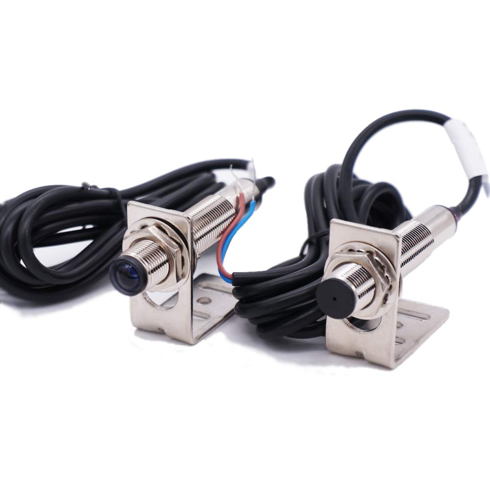
A photoelectric sensor (a device that uses a light beam — usually infrared — to detect whether an object is present) sounds simple until you’re staring at a distributor page with fourteen variants and a datasheet in one hand and an unanswered machine spec in the other. Get the sensing mode wrong and you’ll fight nuisance trips for months. Get the output type wrong and your PLC input card won’t see a signal at all. This guide decodes the three core detection modes — through-beam, retroreflective, and diffuse — and then walks you through NPN versus PNP output selection so you can make one correct decision on the first purchase order, not on the third.
| EDITOR'S PICKBG-38N Photoelectric Sensors | Mid-tierTaiss/Indoor Wall Mounted Photo… | Budget pickTaiss photoelectric Sensor 30cm… | |
|---|---|---|---|
| Sensing Range | 350mm | 5m | 30cm |
| Supply Voltage | 10–30VDC | 12–240VDC | 6–36VDC |
| Output Type | NPN | — | PNP NO |
| Detection Mode | Diffuse | Retro-reflective | Diffuse |
| Background Suppression | ✓ | ✗ | ✗ |
| Housing Style | — | — | M18 |
| Price | $29.98 | $24.99 | $12.99 |
| See on Amazon → | See on Amazon → | See on Amazon → |
The Three Sensing Modes: What They Are and When Each Wins
Every photoelectric sensor works by emitting light and evaluating what comes back (or what stops arriving). The difference between modes is where the receiver lives and how the detection logic is structured.
Through-Beam (Separate Emitter and Receiver)
In a through-beam arrangement, the emitter and receiver are two separate housings mounted on opposite sides of the detection zone. The sensor triggers when a target interrupts the beam between them.
Why you’d choose it: Through-beam gives you the longest sensing range and the highest immunity to ambient light and surface variation. Keyence’s photoelectric sensor fundamentals guide puts typical through-beam ranges at 0.1 m up to 60 m or more for standard infrared models, versus 0.1–15 m for retroreflective and 5 mm–1 m for most diffuse types. If you’re detecting objects on a high-speed conveyor at 10 m across an aisle — or detecting opaque packaging regardless of color or finish — through-beam is the mechanically correct answer.
The tradeoff you’ll actually feel: Two cable runs, two mounting brackets, two alignment tasks. On a retrofit where conduit is already full, the wiring cost can exceed the sensor cost. Alignment drift from thermal expansion or vibration can cause nuisance trips on longer spans. Banner Engineering’s sensing mode selection guide recommends through-beam whenever the sensing range exceeds what retroreflective can deliver reliably, or when the target is partially transparent (films, glass, liquids in clear bottles).
Retroreflective (Emitter and Receiver in One Housing, Reflector on the Far Side)
The emitter and receiver share a single housing. Light travels out to a corner-cube retroreflector (the prismatic target you mount on the opposite surface) and returns to the same unit. An object in the beam path breaks the return signal.
Why you’d choose it: One cable run, one housing to mount and wire. Retroreflective is the pragmatic middle ground for most general-purpose detection at ranges up to 9–15 m. Sick AG’s photoelectric sensor documentation describes the corner-cube reflector’s geometry as returning light almost exactly along the incoming path, which is what makes single-housing detection practical at meaningful distances — a flat mirror can’t do this because the return angle changes with small misalignments.
The tradeoff you’ll actually feel: Shiny or reflective targets can fool a retroreflective sensor into “seeing” the target as though it were the reflector — especially mirrored metal cans or glossy packaging. If your target is specular (mirror-like), you’ll need a polarizing filter kit (sometimes called a “polarization set”) which some manufacturers supply as an accessory, or you move to through-beam. Also: the reflector gets dirty in harsh environments. Budget for a cleaning schedule or an IP69K-rated reflector.
Diffuse (Proximity Mode — Everything in One Housing, No Separate Reflector)
The emitter and receiver share one housing, and detection depends on light reflected directly off the target surface back to the receiver. No reflector is required.
Why you’d choose it: Simplest installation possible — one housing, one cable run, no alignment target on the far side. Ideal when you can’t mount anything across from the sensor (inside a chute, above a conveyor where the far side is open space, or in tight machinery cavities). Control Engineering’s feature on photoelectric sensor selection notes that diffuse mode is the dominant choice for short-range object detection in packaging, assembly, and robotics end-of-arm tooling.
The tradeoff you’ll actually feel: Detection distance is heavily dependent on target color and surface finish. A matte black target may return only 5–10% of the light that a matte white target returns — which collapses your reliable sensing range dramatically. Machine Design’s photoelectric sensing comparison article points out that this is where “background suppression” diffuse sensors earn their cost premium: they use triangulation or dual-zone evaluation to ignore the conveyor surface or wall behind the target, detecting only within a fixed window regardless of color. If your targets vary in color or shade, background suppression diffuse is worth the extra $30–80 per unit over standard diffuse.
By the Numbers: Mode Comparison at a Glance
| Mode | Typical Range | Separate Components | Reflective Target Risk | Relative Install Complexity |
|---|---|---|---|---|
| Through-Beam | 0.1 m – 60 m+ | Yes (2) | None | High (2 cable runs, alignment) |
| Retroreflective | 0.1 m – 15 m | Yes (1 + reflector) | High on shiny targets | Medium |
| Diffuse (standard) | 5 mm – 1 m | No | N/A (target IS the reflector) | Low |
| Diffuse (background suppression) | 5 mm – 500 mm | No | Low | Low |
Ranges and parameters sourced from Keyence, Omron, Banner Engineering, and Sick published datasheets; verify against the specific part number for your application.
NPN vs. PNP Output: The Decision That Trips Up Everyone Once
Once you’ve chosen your sensing mode, the next decision that kills procurement cycles is output type. Most photoelectric sensors ship with either an NPN (also called “sinking”) or PNP (also called “sourcing”) transistor output — and a few offer both on a single unit, selectable by wiring or DIP switch.
What these terms actually mean:
-
NPN (sinking): When the sensor detects a target and activates, it connects the output wire to the circuit’s negative rail (0 V / common). The load — your PLC input, relay coil, or indicator — is wired between the positive supply and the output pin. Current flows into the sensor output. This is “sinking” because the sensor absorbs current.
-
PNP (sourcing): When active, the sensor connects the output wire to the positive supply voltage (typically 12 V or 24 V DC). The load is wired between the output pin and common/ground. Current flows out of the sensor output. This is “sourcing” because the sensor supplies current.
Which one do you need?
The answer is almost always determined by your PLC or input card, not the sensor itself. Check your controller’s input card documentation first:
- Most Siemens S7 and Allen-Bradley CompactLogix/ControlLogix NPN input cards expect a sinking sensor (NPN) — the card supplies voltage internally and the sensor pulls the line low.
- Many Mitsubishi FX and Omron CJ/CP series controllers default to PNP (sourcing) inputs.
- In European and Asian automation contexts, PNP tends to dominate; North American contexts historically leaned NPN, though modern PLCs often support both with jumper selection.
If your site already has deployed sensors, match what’s installed. Mixing NPN and PNP on the same input card without a relay or buffer in between is a wiring fault that can damage input modules.
The NPN/PNP floating decision (when you haven’t chosen a PLC yet):
If you’re designing from scratch, PNP sourcing has become the de facto choice for new industrial designs as of the mid-2020s. Omron’s E3Z series datasheet notes PNP output as the default catalog variant in most regions, and Banner Engineering’s sensor selection guide reflects the same industry-wide shift. The reasoning is safety: a wire-to-ground fault on a PNP sourcing output will drive the output low (safe state), whereas a wire-to-ground fault on an NPN sinking output can inadvertently trigger the load.
Dual-output (NPN+PNP) sensors: Several manufacturers — including Keyence, Balluff, and Sick — offer models where both output types are available simultaneously or selectable via wiring configuration. These cost $10–$40 more per unit but eliminate the “ordered the wrong variant” problem on multi-site or multi-PLC installations. For MRO stocking, a dual-output part number can collapse your SKU count meaningfully.
Light-On vs. Dark-On: The Other Output Mode Decision
While you’re specifying output type, you’ll also encounter Light-On (L-ON) and Dark-On (D-ON) — sometimes labeled NO (normally open) and NC (normally closed).
- Light-On / NO: Output activates when the sensor receives the beam or reflected light. In diffuse mode, this means the output energizes when a target is present.
- Dark-On / NC: Output activates when the beam is interrupted or reflected light is absent. In through-beam mode, this means the output energizes when a target blocks the beam.
Most sensors ship as Light-On / NO, and most applications (detect presence → trigger action) are served by that default. However, if your safe-state logic requires the output to be energized in normal operation and de-energize on detection (common in safety-adjacent applications), you want Dark-On / NC — or a sensor with a switch that toggles between both.
Decision Rules: If X, Then Y
If you’re closing out a BOM or spec sheet right now, run through these in order:
Sensing mode:
- Sensing range > 3 m, or target is transparent/film/liquid → Through-beam
- Sensing range 0.5–9 m, target is opaque, installation allows a reflector → Retroreflective (add polarizing filter if target is specular)
- Sensing range < 1 m, can’t mount anything across from sensor, installation simplicity is the priority → Diffuse (upgrade to background suppression if targets vary in color or if the background is within 2× the sensing range)
Output type:
- PLC/input card already specified → match the card’s input type exactly (check the card manual, not assumptions)
- Designing new → PNP sourcing as the default unless you have a specific reason not to
- Multi-site MRO stocking or uncertain PLC environment → dual NPN/PNP selectable part number
Light-On vs. Dark-On:
- Default to Light-On / NO unless your safety or logic scheme requires the output energized at rest
Environmental rating:
- Wash-down, chemical exposure, or outdoor → confirm IP67 minimum; food processing → IP67 or IP69K with stainless or nickel-plated housing
The three sensing mode questions and the NPN/PNP question are independent — answer them separately, then cross-reference the manufacturer’s configurator to find a part number that satisfies both. Keyence, Banner Engineering, Sick, and Omron all publish online parametric configurators as of mid-2026 that let you filter by mode, output type, range, and IP rating simultaneously, which is the fastest way to get from spec to part number without sifting through 40-page catalogs.
Get the sensing mode right first. The output type question has a lookup table answer once your controller is known. That order of operations will save you the return-shipping cycle.