Imagine you’re standing in front of a packaging line that just started dropping false rejects. Somewhere on that line, a sensor — a small electronic device that detects the presence, distance, or position of an object and sends a signal to a controller — is lying to your PLC. You have three sensor technologies in the cabinet and a $25 handheld tester in your bag. How do you decide which sensor type was right for this application in the first place, and how do you know if the tester is actually telling you the truth? That’s what this article is about. If you’re a controls or automation engineer with a live commissioning job, an MRO replacement order pending, or a troubleshooting ticket open right now, the goal here is to save you the two hours of forum-digging and give you the selection logic and field tradeoffs in one place.
| EDITOR'S PICKTaiss/1 Pair photoelectric Swit… | Mid-tierTaiss/Indoor Wall Mounted Photo… | Budget pickTaiss photoelectric Sensor 30cm… | |
|---|---|---|---|
| Detection type | Through-beam | Retroreflective | Diffuse |
| Range | 0-20M | 5M | 30cm |
| Output type | NPN NO | — | PNP NO |
| Supply voltage | 6-36V | 12-240VDC / 24-240VAC | 6-36VDC |
| Wiring | — | — | Three Lines |
| Housing style | — | Wall Mounted | M18 |
| Price | $27.99 | $24.99 | $12.99 |
| See on Amazon → | See on Amazon → | See on Amazon → |
Through-Beam, Retroreflective, and Diffuse: Picking the Right Mode Before You Buy
Every photoelectric sensor falls into one of three operating modes, and the wrong choice at spec time is the single biggest source of field headaches. Here’s how each one works and where each one breaks.
Through-beam sensors split the emitter and receiver into two separate housings. The object interrupts a beam traveling between them. This gives you the longest sensing range and the most immune signal — nothing but a physical obstruction triggers the output. The tradeoff is installation: you’re running conduit to two locations, aligning two devices, and doubling your mounting labor.
One alignment insight that experienced buyers consistently flag is the value of a visible laser emitter in a through-beam unit. Aligning an infrared (IR) beam — light outside the visible spectrum — across a 16-foot span inside a dim conveyor tunnel is effectively guesswork; you’re aiming at nothing you can see. A visible red laser dot, by contrast, gives you an immediate physical target. Sensors Magazine’s feature on long-range photoelectric alignment explicitly notes that visible-wavelength emitters cut alignment time in multi-meter installations by removing the need for separate alignment tools or secondary indicators. If your installation spans more than roughly 3–4 meters in a low-ambient-light environment, specify a visible emitter rather than assuming IR is the default.
Retroreflective sensors put the emitter and receiver in a single housing and rely on a corner-cube reflector (a tape or disk target that bounces light straight back regardless of angle) mounted on the opposite side of the detection zone. One housing, two cable runs avoided — a real installation win. The catch reviewers and field users most consistently raise: retroreflectors are sensitive to highly reflective objects. A shiny object passing through the beam can return enough light to look like the reflector itself, causing the sensor to ignore the object entirely. This is the “false pass” failure mode, and it’s the reason retroreflective sensors often specify a polarizing filter as a standard accessory. Check your application for glossy film, mirror-finish metal parts, or wet surfaces before defaulting to retro.
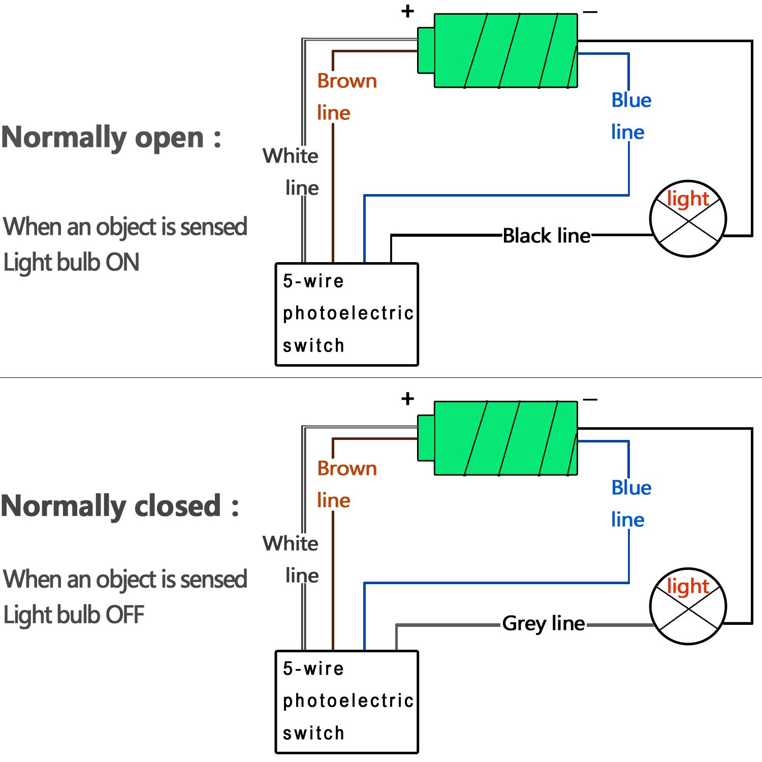
A field note worth surfacing: at least one documented buyer review (aggregated across distributor and reseller platforms) identifies an undocumented second potentiometer on a retroreflective unit that inverts output polarity — switching the output from normally-open to normally-closed behavior. This is not a defect; it’s a deliberately designed polarity-inversion trim that some manufacturers include but don’t always call out in quick-start documentation. If your PLC logic suddenly inverts after a sensor swap, check for a secondary pot before assuming a wiring error.
Diffuse sensors detect the light reflected off the target object itself — no separate reflector required. One housing, one mounting surface, minimal wiring. The tradeoff is that sensing range and reliability depend entirely on the target’s surface color, texture, and reflectivity. A matte black surface absorbs light and shrinks your effective range; a white surface extends it. Banner Engineering’s Sensor Selection Guide quantifies the typical variation: a diffuse sensor rated for 300 mm on a 90%-reflectance white card may only reach 50–80 mm on a dark matte surface. Always derate diffuse range specs against your actual target material, not the datasheet white-card standard.
On cross-compatibility: field experience documented in owner reviews confirms that diffuse sensors are often form-factor and electrically equivalent across manufacturers when key specs match — output type (NPN/PNP), supply voltage, connector pinout, and housing dimensions. One owner documented replacing an OEM automatic chicken-coop door sensor (a low-stakes but illustrative example) with a unit from a different brand that shared the same M18 housing, 10–30 V DC supply, and PNP normally-open output — and the replacement performed identically. The practical implication for MRO buyers: if your OEM sensor is discontinued, a cross-reference on output type, voltage range, housing form factor, and connector pinout will usually get you a functional replacement, even from a different manufacturer. Sick AG’s product family overview and Keyence’s fundamentals guide both note that IEC 60947-5-2 defines enough of the electrical interface that cross-brand PNP/NPN substitution is usually straightforward at the electrical level.
Sensor Testers: What a $20–$30 Tool Actually Tells You (and What It Doesn’t)
A proximity and photoelectric sensor tester is a handheld device that applies a DC supply voltage to a sensor’s input pins and reads back the output state — typically indicating whether the output is switching, and sometimes displaying supply current draw. For a $20–$30 investment, it’s one of the highest-leverage tools in a field technician’s bag.
What it catches reliably:
- Dead sensor: no output state change, no supply draw
- Output wiring polarity issues: NPN vs. PNP mismatch evident immediately
- Basic wiring faults: one documented reviewer describes diagnosing a crankshaft position (CKP) sensor wiring issue on a vehicle by using a generic sensor tester to confirm signal presence at the connector — a five-minute diagnosis that saved a dealership trip
What it doesn’t catch:
- Signal dropout under vibration: a second reviewer explicitly documents this gap. The tester applies a static test voltage and reads a static output — it has no mechanism to detect intermittent dropout caused by a fractured internal connection that only fails under mechanical vibration. If you suspect vibration-induced intermittent faults (a common failure mode on presses, conveyors with significant structural resonance, or mobile equipment), the tester will pass the sensor clean every time. You need a data-capture device — a logic analyzer, oscilloscope, or PLC event log — to catch vibration-induced dropout.
- Response speed: the tester cannot evaluate switching frequency. One buyer documented attempting to use a through-beam sensor for a fast-ball sport timing application and finding it too slow. Response-speed limitations are a published-spec parameter — confirm switching frequency (Hz) and response time (ms) from the datasheet against your application’s required detection window.
By the Numbers: Sensor Mode Tradeoffs at a Glance
| Mode | Typical Range | Installation Complexity | Key Vulnerability |
|---|---|---|---|
| Through-beam | Up to 60 m | High (2 housings, alignment) | Wiring cost; alignment time |
| Retroreflective | Up to 10 m | Medium (1 housing + reflector) | Shiny targets, reflector contamination |
| Diffuse | Up to 1 m typical | Low (1 housing, no reflector) | Target-color/material dependence |
Ranges per Keyence Photoelectric Sensor Fundamentals guide; actual values vary by product family.
Sensitivity Adjustment, Output Polarity, and Practical Wiring Notes
Adjusting diffuse sensitivity for a specific material — sawdust, for example — is a common field question. The procedure is consistent across most manufacturers: with the target material present at your intended detection distance, rotate the sensitivity potentiometer clockwise until the output LED just switches on, then back off roughly 15–20% to build in a noise margin. Sawdust and similar low-reflectivity, variable-density materials benefit from background suppression (BGS) diffuse variants, which use triangulation geometry to reject light from beyond a set distance. Machine Design’s application note on sensor selection explicitly recommends BGS for granular or dusty materials where the background surface and the target material have similar reflectivity — a setup where a standard diffuse sensor will chatter or miss entirely.
Output to relay board wiring is a question that catches newer integrators: can you connect a PNP or NPN transistor output directly to a relay board input without additional components? The short answer is usually yes for relay boards with optically isolated inputs rated at 5–24 V DC and designed for transistor-output sensors — the input impedance is high enough that the sensor’s output transistor isn’t overloaded. The risk case is a relay board with a low-impedance coil driven directly from the sensor pin, with no fly-back diode on the coil. Omron and Banner Engineering both note in their output wiring documentation that inductive loads (relay coils) without suppression diodes can generate voltage spikes that destroy the sensor’s output transistor. Standard practice: always place a fly-back diode across the relay coil, or use a relay board that includes built-in suppression.
Conveyor speed and retroreflective sensor response: Automation World’s 2024 plant-floor diagnostics piece notes that retroreflective sensors used on conveyor applications typically require a switching frequency of at least 500 Hz to reliably detect small parts at belt speeds above 0.5 m/s. Verify your selected sensor’s published response time against: detection object size (mm) ÷ belt speed (mm/ms) = minimum required response window (ms). If your sensor’s response time exceeds that window, you’ll get missed detections — the object passes through the beam faster than the sensor can register the transition.
Decision Rules: If X, Then Y
If your application requires detection across more than 3 meters and alignment access is difficult: specify through-beam with a visible-wavelength emitter. The alignment time savings pay back the dual-housing cost in most installations.
If you need one-sided mounting and your targets are non-glossy: retroreflective is the right default. Add a polarizing filter if any target in the application has a glossy or mirror surface.
If your targets are variable materials or colors and your sensing range can stay under 300 mm: diffuse with background suppression handles the most material-variation cases reliably. Derate the range spec by 50–70% from the white-card datasheet value for dark or matte materials.
If you’re troubleshooting an intermittent fault and the sensor tester shows a clean output: assume the tester is correct but insufficient. Log the output signal under operating conditions — vibration, temperature cycling, or actual product flow — before condemning or replacing the sensor.
If you’re doing an MRO cross-brand replacement: match output type (NPN/PNP), supply voltage range, housing form factor (M12/M18/etc.), connector pinout, and switching frequency. Brand differences at that spec level rarely matter electrically.
Frequently Asked Questions
Why is a visible laser through-beam sensor easier to align than an infrared one? IR light is invisible to the human eye. Aiming an IR emitter at a receiver housing 5+ meters away requires either a secondary optical indicator, an IR viewer, or significant trial-and-error. A visible red laser gives you a physical dot you can place precisely on the receiver aperture in seconds. Sensors Magazine’s alignment feature notes this as a primary selection criterion for any through-beam installation over 3 meters. The specification to look for is listed as “visible red” in the emitter wavelength column of the datasheet, typically 630–680 nm.
Can I connect a photoelectric sensor output directly to a relay board without additional components? Usually yes, if the relay board has optically isolated inputs designed for transistor-output sensors and includes built-in fly-back suppression on the coil side. If the board drives a bare relay coil without suppression, add a fly-back diode across the coil terminals. Running a sensor output into an unsuppressed inductive load is the most common cause of premature output transistor failure in field installations.
What does a proximity/photoelectric sensor tester actually test, and what can’t it catch? A basic tester applies supply voltage and reads output switching state — confirming the sensor is alive, the output is correct polarity, and basic wiring is sound. It cannot detect intermittent dropout under vibration, signal degradation at edge-of-range, or switching speed limitations. One reviewed tester was explicitly noted by its buyer to miss vibration-induced faults entirely. For dynamic fault capture, use a logic analyzer, oscilloscope, or PLC diagnostic log.
How do I adjust sensitivity on a diffuse sensor to detect a specific material like sawdust? Place the actual target material at your intended detection distance. Rotate the sensitivity pot clockwise until the output just switches, then back off 15–20% for noise margin. For low-reflectivity or variable-density materials, prefer a background-suppression (BGS) diffuse sensor over a standard fixed-threshold diffuse — BGS rejects distance variation that causes standard diffuse sensors to chatter with granular or airborne materials.
Are retroreflective sensors fast enough for moving conveyor applications? For most standard conveyor speeds (under 0.5 m/s) and part sizes above 20 mm, yes — most retroreflective sensors rated at 500 Hz or better are adequate. For high-speed lines, calculate the minimum response window as: part size (mm) ÷ belt speed (mm/ms). If your sensor’s published response time (ms) exceeds that window, you will miss detections. Verify the spec before installing, not after commissioning.
Can a diffuse sensor from one brand replace an OEM sensor from a different manufacturer? In most cases, yes — provided the replacement matches on: output type (NPN or PNP), supply voltage range, housing form factor and thread size, connector pinout, and switching frequency. IEC 60947-5-2 standardizes enough of the electrical interface that cross-brand substitution is routine in MRO contexts. One documented owner replacement (an automatic door sensor swap) confirmed functional equivalence across brands on a matched-spec basis. Always confirm the pinout against both sensor datasheets before wiring.