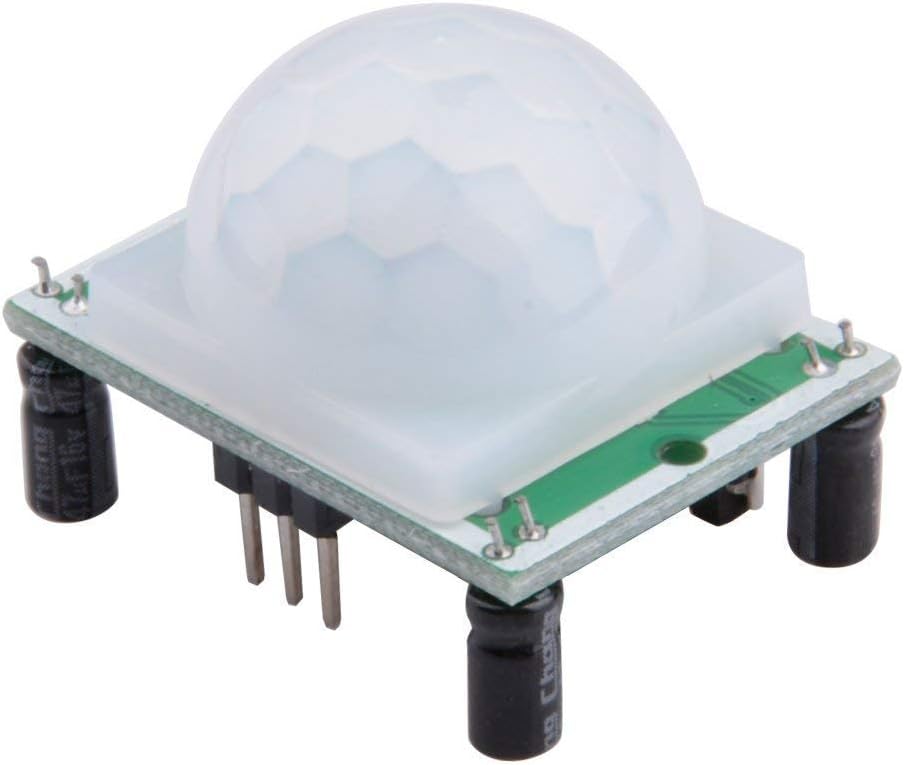
If you’ve ever set up a security camera and wished you could add a trigger that only records when someone actually walks into frame — without paying for cloud storage or a subscription — a PIR motion sensor (Passive Infrared sensor, a device that detects the heat signature of a moving person or animal) is the answer. The HC-SR501 is the dominant entry point: a $1–$3 module that pairs with a Raspberry Pi (a small Linux computer on a single board) or Arduino (a microcontroller development board) to produce a digital HIGH signal whenever warm-body motion crosses its field of view. It’s on tens of millions of boards worldwide, its schematic is open, and it’s stocked by virtually every electronics distributor. But mid-project, builders reliably hit the same three walls: the delay timer behaves nothing like the label suggests, detection range drops noticeably in a warm room, and the output pin can’t directly drive anything heavier than a microcontroller GPIO line. This guide maps those limits precisely, compares the HC-SR501 to the AM312 compact alternative, and gives you wiring patterns for relay and LED loads so you can finish the build you actually started.
What the HC-SR501 Datasheet Actually Tells You (and What It Doesn’t)
The HC-SR501 is built around the BISS0001 PIR controller IC. Per the BISS0001 published specification sheet, the IC has two configurable time constants: Tx (trigger-hold delay) and Ti (inhibit/block time). On the HC-SR501 breakout, Tx is set by the blue trimpot (small adjustable resistor) labeled “Time Delay Adjust,” and a second trimpot sets sensitivity (detection range up to roughly 7 meters at 20°C).
The timing problem buyers hit: The HC-SR501 datasheet lists delay range as approximately 0.5 seconds to 200 seconds (around 3.3 minutes). However, aggregated buyer reviews across multi-pack listings consistently describe the maximum achievable delay at full clockwise rotation as landing in the 2.5–3 minute range, not the “up to 30 minutes” figure that appears in some third-party summaries and tutorial blog posts. That 30-minute figure is not sourced to the BISS0001 datasheet or any HC-SR501 OEM spec sheet — it appears to be a persistent copy error. If your project requires delays longer than 3 minutes, plan to extend hold time in firmware rather than relying on the hardware potentiometer.
The temperature problem: The HC-SR501 datasheet explicitly states that detection range is rated at an ambient temperature of approximately 20°C (68°F). A buyer citing the datasheet directly in a Digi-Key review noted that range degrades meaningfully as ambient temperature approaches 30°C (86°F), because the thermal contrast between a human body (~37°C surface radiation) and the background narrows. At 35°C ambient in a non-air-conditioned workspace or summer outdoor enclosure, you can expect detection range to fall below the rated 7 meters — some owners report reliable triggering only within 3–4 meters under those conditions. This is physics, not a defect, but it should be in your design budget when choosing mounting height and coverage angles.
By the numbers — HC-SR501 key specs:
| Parameter | Rated Value | Notes |
|---|---|---|
| Supply voltage | 4.5V – 20V DC | Wide range; 5V typical on Arduino/Pi |
| Output voltage (HIGH) | ~3.3V (at 5V supply) | Check your datasheet revision |
| Max output source current | ~10 mA | Cannot drive relay coils or LEDs directly |
| Detection range | Up to 7m @ 20°C | Degrades toward 30°C ambient |
| Delay range (Tx pot) | ~0.5s – ~200s | Max ~3 min in practice; not 30 min |
| Field of view | ~120° cone | Fixed Fresnel lens on most modules |
Per the HC-SR501 generic OEM specification sheet, the output stage is an open-collector-compatible push-pull driver rated at approximately 10 mA source current. That number matters the moment you want to drive anything beyond a GPIO pin.
Wiring for Real Loads: LEDs, Relays, and Microcontrollers
Direct GPIO Connection (Arduino / Raspberry Pi)
For an Arduino digital input or Raspberry Pi GPIO input (rated at 3.3V logic per the Raspberry Pi Foundation Hardware documentation), the HC-SR501 output pin connects directly with no additional components. One wire from OUT to your digital pin, common GND, and 5V to VCC. The output HIGH on a 5V-powered HC-SR501 is typically 3.1–3.3V — safe for a 3.3V Raspberry Pi GPIO input, but verify against your specific module’s output spec because some revisions do push closer to VCC.
Driving an LED
Multiple owners across HC-SR501 multi-pack reviews flag this the hard way: the output pin cannot reliably sustain an LED without a series resistor and it will stress the IC at the 10 mA limit even if the LED lights dimly. The correct approach is a 470Ω to 1kΩ series resistor between the OUT pin and the LED anode, with cathode to GND. This keeps current under 5 mA and keeps the BISS0001 output stage well within spec. Do not wire the LED directly pin-to-GND with no resistor.
Driving a Relay Without a Microcontroller
This is the most commonly asked wiring question in owner reviews, and it requires a small NPN transistor circuit. A standard 2N2222 or BC547 works well:
- HC-SR501 OUT pin → 1kΩ resistor → NPN base
- NPN collector → relay coil negative terminal
- Relay coil positive terminal → 5V supply
- NPN emitter → GND
- Flyback diode (1N4148 or 1N4007) across the relay coil terminals, cathode toward 5V
This configuration draws only ~1 mA from the HC-SR501 output while switching whatever current the relay coil requires (typically 50–70 mA for a 5V SRD-series relay). One owner using the sensor to trigger a garage light relay reported that without this transistor stage, the module would output a brief pulse and then lock up — consistent with an output-pin overcurrent condition. The transistor stage fixes this cleanly. Power the HC-SR501 from the same 5V rail as the relay coil and use a common ground.
HC-SR501 vs. AM312: When to Choose Which
The AM312 is a compact alternative — roughly the size of a TO-92 transistor package with a built-in micro Fresnel lens — and it behaves quite differently. Per the Senba Sensing Technology AM312 datasheet, the module is fixed: no potentiometers, no adjustable delay, no sensitivity trim. It outputs a fixed ~2-second pulse on detection, and — critically — its output is always 3.0–3.3V regardless of supply voltage, even when powered from 5V. This is both a safety feature (zero risk of over-voltage on a 3.3V Raspberry Pi GPIO) and a hard constraint (no extending delay time in hardware).
Decision rule:
- If you need adjustable hold time, higher detection range, or will operate in a controlled-temperature indoor environment below 25°C: use the HC-SR501. Its trimpots give you project-to-project tuning flexibility, and its wider detection cone works better for room-coverage applications.
- If you’re building a small form-factor device, need direct 3.3V GPIO compatibility with no level-shift concerns, and can accept a fixed ~2s pulse: the AM312 is cleaner to integrate and harder to blow up. Reviewers using it with Raspberry Pi Zero builds specifically cite the fixed 3.3V output as the reason they chose it over the HC-SR501.
The WWZMDiB multi-pack HC-SR501 kits that include plexiglass standoff mounts and a trim screwdriver are worth calling out for build contexts where repeatable sensor positioning matters — reviewers on multi-pack listings specifically note that the mounts allow consistent pointing angle across multiple identical sensor nodes in a multi-room installation, which reduces the re-tuning effort on sensitivity between units.
Practical Build Notes: Reducing False Triggers and Improving Reliability
Single-trigger vs. repeatable-trigger mode: The HC-SR501 has a solder-bridge jumper (sometimes labeled H/L) that selects between two modes. In single-trigger (L) mode, the output goes HIGH once, holds for the Tx delay period, then goes LOW and enters a ~2.5-second inhibit window before it can trigger again — regardless of whether motion is still present. In repeatable-trigger (H) mode, any new motion detected before the delay expires restarts the timer, so the output stays HIGH continuously as long as someone is moving in the detection zone. Most tutorials default to H mode for occupancy applications; use L mode when you want a defined single-pulse output, such as incrementing a counter.
To change modes: locate the three-pin header or solder bridge between the two trimpots. Bridging the outer two pads toward “H” sets repeatable mode; toward “L” sets single-trigger. Some modules ship in L mode, which is why owners report the output dropping out unexpectedly while still standing in front of the sensor.
Reducing false triggers from pets: The HC-SR501’s Fresnel lens pattern covers ~120° horizontally and typically extends down to floor level depending on mounting height. Owners in multi-pet households report two practical mitigations: (1) mount the sensor at or above 2.1 meters (7 ft) and angle it slightly downward to create a detection zone that starts approximately 1–1.5 meters from the floor — most small-to-medium pets move below this band; (2) reduce the sensitivity trimpot to the minimum that still reliably triggers on a standing human at your required range. Per the HC-SR501 OEM specification sheet, the sensitivity pot adjusts detection range from roughly 3 meters (minimum) to 7 meters (maximum) — backing it off from maximum significantly shrinks the vertical detection volume. Neither approach is perfect: large dogs will still trigger at moderate sensitivity. For installations where pet immunity is a hard requirement, a dual-element PIR module with pet-immune Fresnel optics (a separate product category) is the correct tool.
Frequently Asked Questions
Why does my HC-SR501 stay triggered for so long even at the minimum delay setting? The minimum delay (~0.5 seconds) applies only in single-trigger (L) mode. If your jumper is set to repeatable-trigger (H) mode and there’s any residual motion — a fan oscillating, curtains moving, a pet — the timer keeps restarting. Switch to L mode and eliminate background motion sources first. If it’s still stuck HIGH, check for supply voltage noise; a 100µF capacitor across VCC-GND near the module often resolves false-hold behavior.
Can I use the HC-SR501 outdoors in summer without it losing detection ability? You can, but plan for degraded range. The HC-SR501 datasheet rates performance at ~20°C. As the Digi-Key review citing the datasheet directly noted, range degrades toward 30°C ambient. At 35°C+ in an unshaded summer enclosure, expect reliable triggering only within 3–4 meters rather than the rated 7. Use maximum sensitivity setting, keep mounting height moderate, and if possible orient the sensor away from direct sun-heated surfaces that create thermal gradients in the detection zone.
How do I wire the HC-SR501 to trigger a relay without an Arduino? Use the NPN transistor circuit described in the wiring section above: HC-SR501 OUT → 1kΩ → NPN base; collector to relay coil; emitter to GND; flyback diode across the coil. The HC-SR501 drives only the transistor base (~1 mA), not the relay coil directly.
What is the difference between single-trigger and repeatable-trigger mode and how do I change it? Single-trigger (L): one pulse per detection event, then inhibit window. Repeatable-trigger (H): timer resets with each new motion, output stays HIGH continuously while motion persists. Change via the H/L solder jumper or three-pin header between the trimpots on the module.
Will the AM312 output voltage damage a 3.3V Raspberry Pi GPIO pin? No. Per the Senba Sensing Technology AM312 datasheet, the output is fixed at 3.0–3.3V regardless of supply voltage. The Raspberry Pi Foundation Hardware documentation rates GPIO inputs at 3.3V maximum; the AM312 output is within that range and is commonly recommended precisely for direct Pi GPIO connections.
How do I reduce false triggers when using PIR sensors near pets? Mount above 2.1 meters and angle downward; reduce the sensitivity trimpot from maximum; use single-trigger mode to avoid continuous re-triggering from small movements. For strict pet immunity, purpose-built pet-immune PIR modules with matched Fresnel optics are the more reliable long-term solution than tuning a standard HC-SR501.
If X, then Y — the decision rule for this module pair:
- You’re building a microcontroller project in a temperature-controlled indoor space and need tunable hold time → HC-SR501 with transistor output stage for any load beyond GPIO.
- You’re building a compact, always-on node directly on a Raspberry Pi GPIO with no adjustment needed → AM312, wired direct, no additional components.
- You need reliable outdoor summer detection beyond 4 meters → Neither module is your primary answer; a dedicated outdoor PIR detector rated for elevated ambient temperatures belongs in that BOM slot.