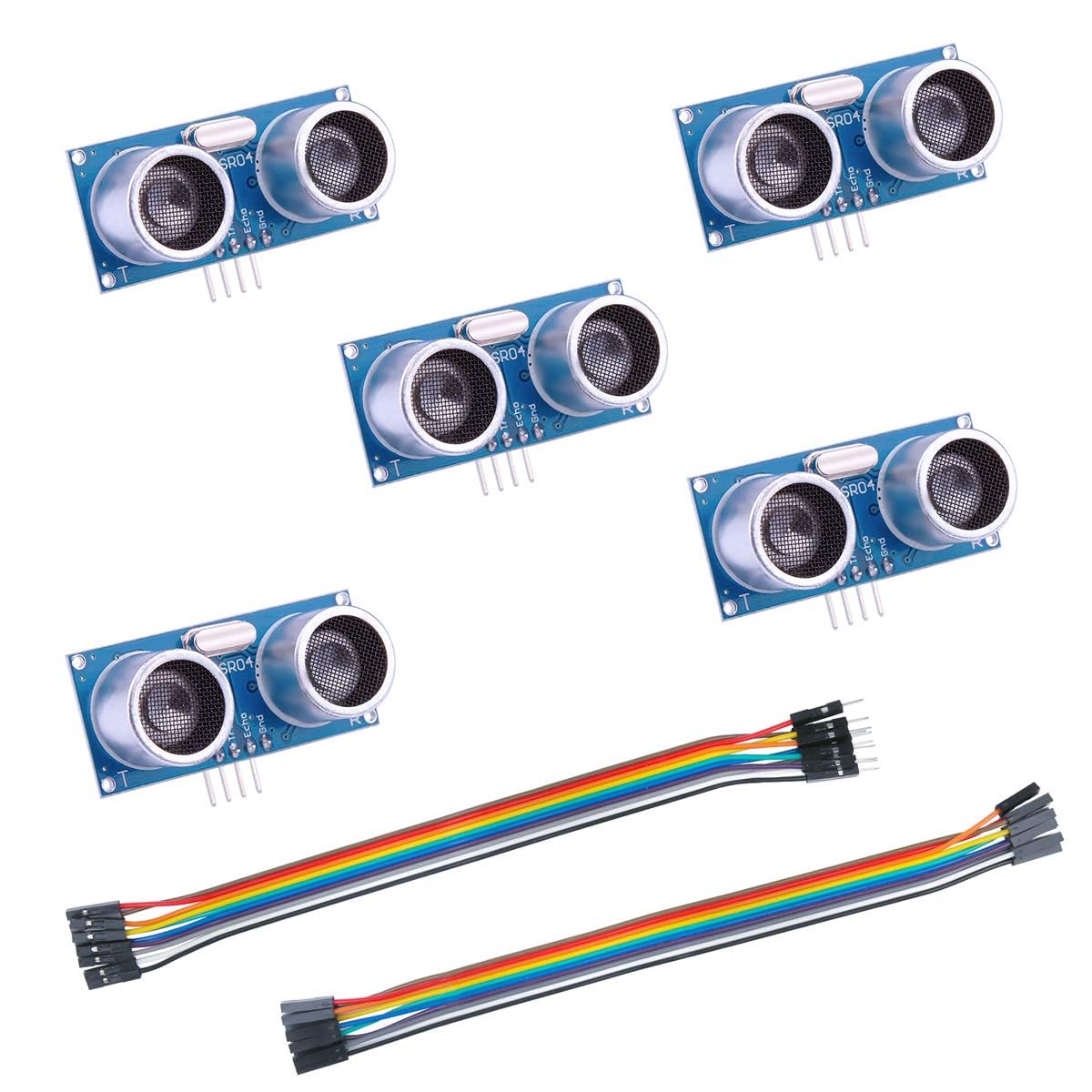
If you’ve ever wired a cheap sensor module to an Arduino and wondered why it behaves nothing like the tutorial promised, you’re in good company. The HC-SR04, HC-SR501, and AM312 are three of the most widely purchased sensor modules in the hobbyist and prototyping world — but they do completely different things, and mixing them up wastes time, burns out pins, and sometimes ruins a project deadline. In plain terms: the HC-SR04 is an ultrasonic distance sensor that uses sound pulses to measure how far away an object is. The HC-SR501 and AM312 are both PIR (passive infrared) motion sensors that detect body heat to sense whether a person has moved through a space. This guide cuts through the noise, shows you the real tradeoffs documented in published datasheets and aggregated buyer reviews, and ends with a direct decision rule so you can make a confident BOM (bill of materials) call today.
What Each Module Actually Does — and Where Each One Breaks Down
HC-SR04: Ultrasonic Distance, Not Motion
The HC-SR04 sends a 40 kHz ultrasonic pulse from its TRIG pin, listens for the echo on its ECHO pin, and measures the time-of-flight. The math is simple: distance (cm) = pulse duration (µs) ÷ 58. Per the manufacturer datasheet, the rated range is 2 cm to 400 cm with a stated accuracy of ±3 mm under ideal conditions. Operating voltage is 5V DC; the module draws roughly 15 mA during burst.
Where reviewers consistently praise it: One of the most detailed real-world use cases that surfaces across product reviews involves outdoor water-level monitoring and bridge-clearance measurement — applications where a non-contact, non-submerged sensor is essential. Owners in those contexts note that mounting stability is the single biggest factor in repeatable readings. This matches advice from the Smraza bracket community: even a 2–3° tilt of the sensor housing shifts the echo return angle enough to introduce centimeter-scale errors in mid-to-long-range measurements. If you’re building a water-level monitor, a rigid, vibration-isolated mount is not optional — it is the calibration.
Where it struggles:
- The module is not waterproof in its stock form. Outdoor use requires either a waterproofed variant (JSN-SR04T) or protective housing.
- At ranges below 2 cm, the transmit burst overlaps the receive window and readings become unreliable.
- Highly absorbent targets (foam, thick fabric, loose grain) scatter the pulse and reduce effective range significantly.
- The ECHO pin outputs at 5V logic, which is a 3.3V GPIO killer on Raspberry Pi, ESP32, or STM32 boards without a voltage divider or level shifter.
Electronic Design’s coverage of ultrasonic sensing fundamentals notes that temperature affects the speed of sound (~0.6 m/s per °C), which means a 20°C ambient swing introduces roughly a 3.5% range error without compensation. For a water-level sensor tracking a 2-meter tank, that’s ~7 cm of uncorrected drift across summer-to-winter conditions.
By the numbers — HC-SR04:
| Parameter | Rated Spec |
|---|---|
| Supply voltage | 5V DC |
| Measuring range | 2 – 400 cm |
| Accuracy (ideal) | ±3 mm |
| Beam angle | ~15° |
| ECHO output logic | 5V (level shift required for 3.3V MCUs) |
HC-SR501: The Workhorse PIR with Real Gotchas
The HC-SR501 uses a BISS0001 signal-processing IC paired with a dual-element pyroelectric sensor beneath a Fresnel lens. It operates on 4.5V–20V, making it comfortable on both 5V Arduino boards and 12V panels. The output pin swings to ~3.3V high on detection — fine for Arduino digital inputs, marginal for some 5V relay modules (more on that below).
The two adjustable trimpots on the back of the board are the source of most user confusion:
- Sensitivity pot — adjusts detection range from roughly 3 m to 7 m.
- Time-delay pot — adjusts the output hold time.
The hold-time question is the single most-asked spec question for this module, and the confusion is legitimate — see the FAQ section below.
The temperature failure mode almost no buying guide mentions: The HC-SR501 datasheet, combined with BISS0001 application notes, documents that PIR detection sensitivity degrades above approximately 30°C ambient because the pyroelectric element responds to the differential in infrared radiation between a moving body and the background. When background temperature approaches body temperature (~37°C), that differential collapses. Sensors Magazine’s PIR application notes confirm this physics: in a hot garage in July, or a summer attic, an HC-SR501 can miss detection events entirely — not because it’s broken, but because the room is too warm for the physics to work. If your deployment environment regularly exceeds 30°C, either choose an active IR or microwave sensor instead, or test the specific unit in-situ before committing.
Trigger modes: The HC-SR501 has a physical jumper (labeled H/L on the PCB) that selects:
- H (repeat trigger): Output stays high as long as motion continues to be detected, resetting the hold timer on each re-trigger event.
- L (single trigger): Output goes high once, holds for the set duration, then goes low regardless of continued motion.
AM312: The Cleaner Choice for 3.3V Systems
The AM312 is a smaller, lower-power PIR module built around the BISS0001 derivative architecture but stripped down: no adjustable pots, fixed sensitivity, fixed hold time (~2 seconds), and — critically — a 2.7V–12V operating range with a 3.3V-compatible output. It draws roughly 12 µA in standby.
That 3.3V output is the clearest single differentiator from the HC-SR501, and it’s the spec that Raspberry Pi, ESP32, and RP2040 users consistently call out in reviews. You get a logic-level signal you can wire directly to a GPIO without any level shifting, resistor dividers, or worrying about whether a 3.3V pin can tolerate a 3.3V-high drive. It just works at the voltage your board actually uses.
Tradeoffs vs. HC-SR501:
- No range or time adjustment. What you get is what you get.
- Smaller detection cone (roughly 100° field of view vs. ~120° on the HC-SR501 with standard lens).
- Shorter hold time (~2 s) with no way to extend it in hardware — you handle hold logic in firmware.
- Physically smaller (useful in tight enclosures, less so for wide-area coverage).
Wiring Reality: What You Can and Cannot Drive Directly from the Output Pin
This is where projects go wrong. Both the HC-SR501 and AM312 output pins are signal outputs, not power outputs. The HC-SR501 output is rated for low current drive — published specs indicate a maximum of a few milliamps at best. The AM312 is similarly constrained.
What you cannot do:
- Wire the output pin directly to a relay coil. Most 5V relay modules draw 60–80 mA on their coil — that will sink far more current than the PIR output pin is rated to source, and you risk damaging the sensor IC.
- Drive a high-brightness LED directly. A standard 5mm red LED needs 20 mA; the output pin cannot reliably supply that.
What you can do:
- Feed the signal into a microcontroller GPIO pin, which draws microamps in input mode. This is the designed use case.
- Use a small NPN transistor (e.g., 2N2222, BC547) as a switch, with the PIR output driving the base through a 1kΩ resistor, and the collector switching your relay or LED from a separate supply rail.
- Use a MOSFET gate driver circuit if you need to switch larger loads.
Per Electronic Design’s transistor switching fundamentals coverage: a 2N2222 with a 1kΩ base resistor driven from a 3.3V or 5V signal will saturate into a 100 mA load with room to spare. That is the correct architecture for this type of sensor output.
Frequently Asked Questions
1. What is the real maximum hold time on the HC-SR501, and why do different sources say different things?
The BISS0001 datasheet specifies the hold-time range as approximately 0.5 seconds to 200 seconds, set by the value of the timing resistor and capacitor on the board. Most HC-SR501 breakout boards use component values that give a practical range of roughly 5 seconds (pot fully counter-clockwise) to 200–300 seconds (pot fully clockwise). The confusion arises because different PCB manufacturers use different RC component values, and many tutorials were written against a specific board revision. The only reliable approach: set the pot to its extremes and time the output with a stopwatch on your specific board before writing any firmware timer logic.
2. Can I use an HC-SR501 or AM312 output to directly drive a relay or LED without a microcontroller?
Not safely, and not reliably. The output pins are signal-level outputs rated for microamp-to-low-milliamp sink/source. A relay coil or LED needs significantly more current. Use the output to drive the base of an NPN transistor (2N2222 or equivalent), which then switches the load from a proper power rail. This is a five-component circuit and the correct engineering answer.
3. Will HC-SR501 PIR sensors stop detecting people in a hot garage or summer attic?
Yes — this is documented physics, not a defect. PIR sensors detect the difference in IR radiation between a moving warm body and the ambient background. When background temperature climbs toward body temperature (~37°C), the differential shrinks and detection becomes unreliable. Sensors Magazine’s PIR application notes confirm this effect. If your environment regularly hits 35°C+, consider a microwave Doppler sensor (e.g., RCWL-0516) or an active IR beam-break system instead.
4. What is the practical accuracy of the HC-SR04 for water level measurement, and can it work outdoors?
Accuracy under calm, controlled conditions aligns with the ±3 mm rated spec, but real-world deployments add error sources: temperature variation (~0.6 m/s speed-of-sound drift per °C), turbulent water surfaces that scatter the echo, condensation on the transducer face, and mounting angle. Outdoor use requires a weatherproof enclosure and ideally a temperature-compensated firmware calculation. Owners who document outdoor water-level projects report practical accuracy of ±1–2 cm in stable conditions — sufficient for tank-level alerts but not for precision metering. The JSN-SR04T waterproofed variant is the correct module choice for any wet or outdoor application.
5. What is the difference between the AM312 and HC-SR501, and which one should I use with a Raspberry Pi?
The AM312 outputs 3.3V logic and runs at 3.3V supply — making it a direct, no-adapter connection to Raspberry Pi GPIO pins. The HC-SR501 outputs nominally 3.3V high from a 5V supply rail, which is usually acceptable on Pi GPIO (rated 3.3V), but the supply voltage mismatch requires running 5V to the sensor while protecting 3.3V GPIO inputs. If you want zero-wiring-drama on a Pi or ESP32, the AM312 is the cleaner choice. If you need adjustable range and hold time, accept the HC-SR501’s wiring complexity.
6. How do I choose between single-trigger and repeat-trigger mode on the HC-SR501 for a Halloween animatronics project?
Use repeat-trigger (H mode) if you want the animatronic to stay active — and keep moving, speaking, or lighting up — as long as someone remains in front of it. The output stays high continuously, and your MCU just reads HIGH = run. Use single-trigger (L mode) if you want a one-shot burst: person walks by, animatronic fires once for exactly your set hold duration, then resets and waits for the next discrete trigger event. For most Halloween props, repeat-trigger creates a more satisfying interaction because the effect doesn’t cut out while the visitor is still standing there. Single-trigger is better for a “jump scare” that should fire once per approach and then pause.
The Decision Rule
If your project needs to measure distance or detect object presence by range → HC-SR04 (with level shifter on 3.3V boards, weatherproof variant for outdoor use, rigid mount as non-negotiable).
If your project needs motion detection with adjustable sensitivity and hold time, on a 5V Arduino ecosystem → HC-SR501, and plan for a transistor switch on any load over 5 mA.
If your project needs motion detection on a Raspberry Pi, ESP32, or any 3.3V MCU with minimal wiring complexity → AM312, accept the fixed 2-second hold in firmware, and use the space and power savings to your advantage.
If your deployment environment is above 30°C ambient and PIR is your intended technology → reconsider the sensor category entirely before you buy either PIR module.
The right module is the one whose published specs match your actual environment. These three are all excellent choices inside their envelopes — and frustrating failures outside them.