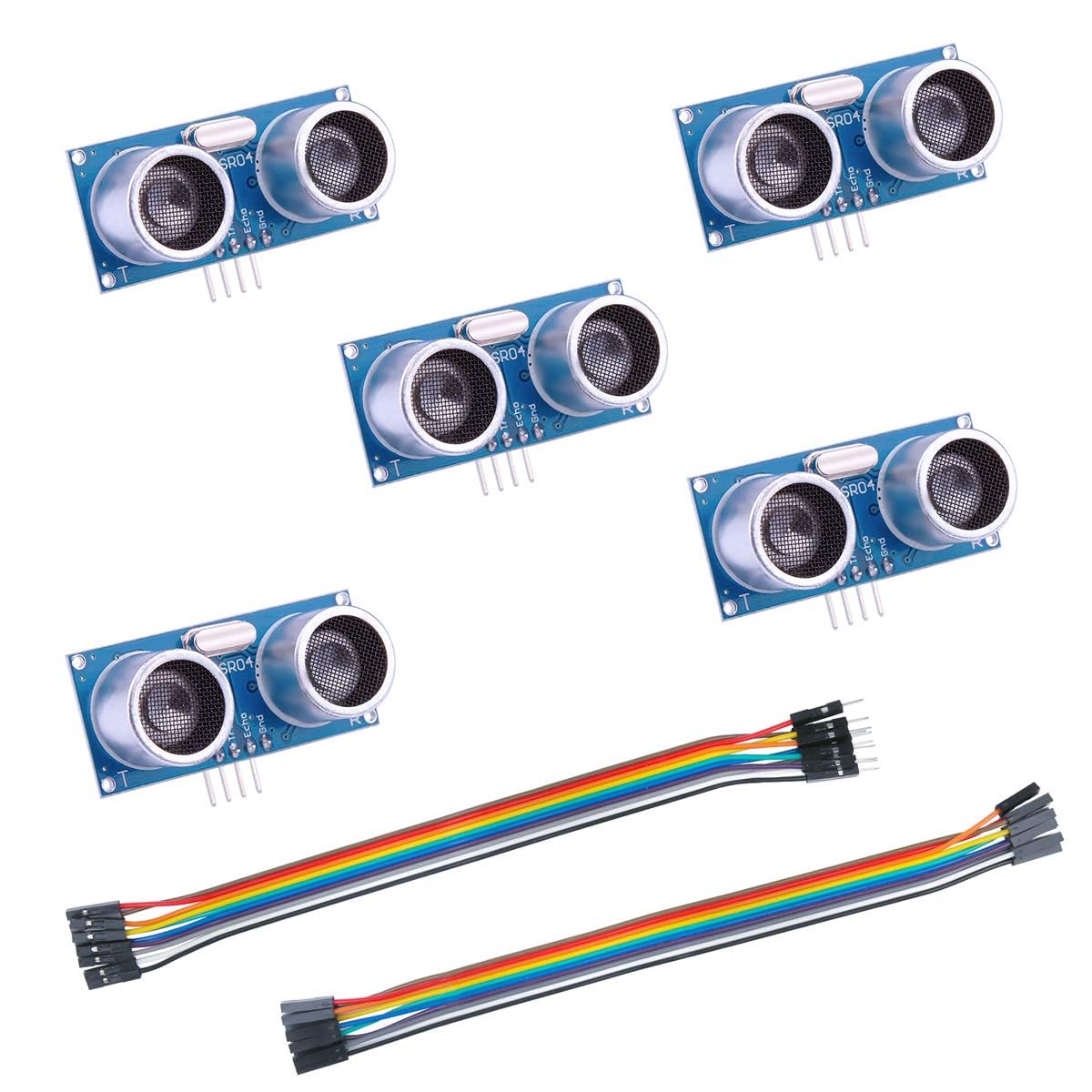
The HC-SR04 is a $3–$10 ultrasonic distance sensor — “ultrasonic” meaning it fires a short burst of sound above the range of human hearing and times how long the echo takes to return, converting that round-trip time into a distance reading. You’ve probably seen it in Arduino starter kits, pointed at a wall on a desk. What’s less well-documented is what happens when practitioners push it into real field conditions: sealed water tanks, outdoor bridge-clearance monitors, and multi-sensor robotics arrays where I2C bus addressing (a two-wire communication protocol that lets many devices share the same signal lines) eliminates pin-count headaches. This guide covers exactly those deployments. You’ll come away with a calibrated sense of real-world accuracy limits, a decision framework for enclosures and mounting, and a clear read on when the standard HC-SR04’s architecture becomes the bottleneck — and what to reach for instead.
| EDITOR'S PICKLonely Binary 5-Pack HC-SR04 Ul… | Mid-tierELEGOO 5PCS HC-SR04 Ultrasonic… | Budget pickSmraza 2pcs Ultrasonic Module H… | |
|---|---|---|---|
| Interface | I2C/UART/1-Wire/GPIO | GPIO | GPIO |
| Voltage | 3.3V/5V | 5V | — |
| PCB color | Gold | — | — |
| Accessories | Brick adapters, case | — | Mounting bracket (2) |
| Uses | Arduino, ESP32 | Arduino, XBee, ZigBee | Arduino, XBee, ZigBee |
| Solderless | ✓ | — | — |
| Price | $14.99 | $7.99 | $6.99 |
| See on Amazon → | See on Amazon → | See on Amazon → |
Real-World Accuracy: What ±1 Inch Actually Means for Your Application
Before committing to any deployment, you need an honest accuracy baseline. Across aggregated owner reviews and published application notes, the consensus is consistent: ±1 inch (approximately ±2.5 cm) over a range of 1–3 meters is the honest figure for the HC-SR04 in non-ideal conditions. The manufacturer datasheet specifies ±3 mm under controlled conditions at room temperature, but that number assumes a perpendicular, hard, flat target at moderate range with stable temperature.
Sensors Magazine’s overview of ultrasonic sensing principles notes that temperature variation is the primary real-world error source: the speed of sound changes roughly 0.6 m/s per °C, and the HC-SR04 applies no temperature compensation internally. At a 20°C ambient swing (not unusual in an outdoor enclosure over a 24-hour cycle), you’re looking at a systematic error approaching 3–4% of measured distance — which at 2 meters works out to 6–8 cm, well beyond the datasheet spec.
By the numbers:
| Condition | Typical Accuracy |
|---|---|
| Controlled lab, 20°C, flat target | ±3–5 mm (datasheet) |
| Stable indoor environment | ±5–10 mm (owner reports) |
| Outdoor / temperature-variable | ±1 inch / ±2.5 cm (owner consensus) |
| Water surface target | ±1–1.5 inches (surface ripple adds noise) |
Multiple reviewers explicitly flag this and call it “good enough” — and it frequently is. Tank fill-level monitoring that triggers a relay when water drops below 20 cm doesn’t need millimeter resolution. A bridge clearance monitor that flags when clearance drops below 3 meters has 25 mm to spare. If your application has tight tolerance requirements (precision dosing, dimensional QC, position feedback in closed-loop control), the HC-SR04 is the wrong sensor family and you should be looking at Pepperl+Fuchs, Microsonic, or Sick ultrasonic transducers with analog 4–20 mA outputs and onboard temperature compensation.
For the applications covered in this guide, ±1 inch is workable. Just model it explicitly in your system design rather than assuming better.
Water Level and Tank Monitoring: What Makes It Repeatable
Water surface measurement is where the HC-SR04 earns its reputation as an overachiever. Owners consistently report deployments measuring tank fill level every 30 minutes for over two years without hardware failure. The key variables that determine whether yours works reliably or produces garbage:
Mounting rigidity is the single most important factor. A reviewer running a long-duration tank installation specifically identifies fixed sensor positioning as the deciding variable for repeatable results. If the sensor can shift even a few millimeters relative to the tank wall between readings, your baseline changes and you’re chasing a moving target. The Smraza mounting bracket pack is praised in owner reviews specifically for solving this — the bracket locks the sensor in a fixed angular and positional relationship to the mounting surface, which is far harder to achieve with foam tape or loose wiring than it sounds.
Enclosure design for tank installations. If the sensor is inside a tank enclosure with high humidity, you have two threats: condensation on the transducer face, which scatters the beam, and corrosion on the PCB traces. Owners running sealed screw-case enclosures (typically a small ABS or polycarbonate IP65-rated project box with the transducer faces protruding through sealed cutouts) report multi-year survival. The critical detail is allowing the transducer faces to protrude and be sealed at the housing penetration — not potting the entire sensor in epoxy, which damps the acoustic element. Silicone gasket compound at the cutout is the standard approach.
Targeting a water surface. Water is acoustically reflective, but ripple is your enemy. Even minor agitation from a pump or fill valve creates a surface that’s no longer flat and perpendicular to the beam. The practical mitigation is a stilling well — a section of pipe or tube submerged in the tank, open at the bottom, that isolates a column of water from the main turbulence. The sensor reads distance to the surface in the stilling well. This is a standard technique documented in Arduino Project Hub’s guide on sensor deployment patterns and is worth the 20 minutes of implementation time.
Outdoor Deployments: Bridge Clearance and Environmental Realities
A common outdoor use case that shows up repeatedly in owner reviews is bridge or overpass clearance measurement — pointing the sensor downward or horizontally to track distance to a water surface (river level under a bridge, for instance) or upward to measure vehicle clearance. These deployments have different enclosure requirements than sealed tanks.
Temperature compensation matters more outdoors. Per Microchip Technology’s AN1168 application note on ultrasonic distance measurement, adding a low-cost NTC thermistor (a resistor whose value changes with temperature, used to measure ambient conditions) to your Arduino and applying a software compensation factor of approximately 0.6 m/s per °C can recover most of the temperature-driven error. At a $0.50 component cost, this is an obvious add for any outdoor deployment targeting better than ±2 cm accuracy.
Power and transmission. Owners running outdoor bridge clearance monitors often pair the HC-SR04 with an Arduino sleep cycle — a low-power mode where the microcontroller cuts most of its current draw between readings. Arduino Project Hub’s documentation on sleep modes covers this pattern: wake, enable the 5V rail to the sensor (the HC-SR04 draws ~15 mA when active), take a reading, store or transmit, power down the sensor, and re-enter sleep. For a battery-powered deployment taking readings every 30 seconds, this architecture can extend a lithium cell from days to months.
Enclosure selection. “Can I just leave it in a plastic box?” is the right instinct but the details matter. The acoustic path has to be clear — which means either a hole in the enclosure (with appropriate baffling to prevent water ingress along the acoustic axis) or a thin membrane of acoustically transparent material. Polyurethane film in the 0.1–0.2 mm range works, though it introduces a small reflection artifact. The more common field approach is a downward-angled cutout with a roof overhang to block direct rain impingement, similar to a louver. One reviewer notes a single unit survived unexpected direct element exposure without failure, but that’s luck, not design intent — don’t design for it.
Running Multiple Sensors: Pin-Count Problems and the I2C Upgrade Path
The standard HC-SR04 uses two GPIO pins per sensor: one trigger pin (sends the ultrasonic pulse) and one echo pin (receives the return signal). On an Arduino Uno with 14 digital pins and several reserved for serial/power, you run out of pins fast. Four sensors consume 8 pins; six sensors leave you with almost nothing for output devices or status LEDs.
The multiplexing approach. You can share trigger pins across sensors (trigger them sequentially, not simultaneously) while keeping dedicated echo pins, cutting pin count to N+1 for N sensors. This works but requires careful timing to prevent crosstalk — the echo from sensor 1 being misread by sensor 2. Minimum safe inter-pulse delay is typically 50–60 ms in a reflective environment; Sensors Magazine’s application notes on ultrasonic crosstalk confirm this as the standard conservative figure.
The I2C upgrade. This is where the Lonely Binary I2C/multi-mode pack enters the picture. I2C (Inter-Integrated Circuit) — the two-wire bus protocol referenced earlier — assigns each sensor a unique address, so all sensors share two signal wires (SDA and SCL) plus power and ground. The practical result: you can run 8+ sensors on two Arduino pins, with addressing handled in firmware. Reviewers in the maker community specifically call out the ability to set unique I2C addresses as the key value proposition for multi-sensor robotics builds.
Per electronicdesign.com’s coverage of I2C bus topologies, the standard I2C bus supports up to 127 unique device addresses, though in practice capacitance limits and signal integrity considerations put practical maximums closer to 10–20 devices on a single bus at standard 100 kHz speed. For an 8-sensor distance array on a robot chassis, this is a non-issue.
The Lonely Binary pack’s inclusion of LEGO-compatible brick mounts isn’t a gimmick for this audience — owners describe it as genuinely useful for rapid mechanical prototyping, particularly in robotics applications where sensor placement needs to be iterated before committing to a machined mount.
Frequently Asked Questions
1. Can I use an HC-SR04 outdoors without a weatherproof enclosure?
One reviewer reports a unit surviving direct element exposure, but this is anecdote, not specification. The HC-SR04 carries no IP rating from its manufacturer. For any outdoor deployment longer than a short test, use a minimum IP54 enclosure with the transducer faces protected from direct rain impingement. The sensor PCB is the vulnerable component; the ceramic transducer elements themselves are relatively tolerant of humidity if the board is protected.
2. How accurate is the HC-SR04 in real use — is ±1 inch typical?
Yes, across owner reviews, ±1 inch over 1–3 meters in variable conditions is the honest consensus. Datasheet claims of ±3 mm apply under controlled lab conditions with temperature stabilized. If you need better than ±1 cm outdoors or in variable-temperature environments, add a thermistor-based temperature compensation routine to your firmware, which can recover 60–70% of temperature-driven error. If you need ±1 mm or better, this sensor family isn’t the right tool.
3. How do I run multiple HC-SR04 sensors on one Arduino without pin conflicts?
Two approaches: sequential multiplexing (share trigger pins, keep individual echo pins, wait 50–60 ms between pings to prevent crosstalk) or an I2C upgrade module like the Lonely Binary pack, which puts multiple sensors on a two-wire bus and handles addressing in firmware. For more than 3–4 sensors, the I2C path is almost always cleaner and more maintainable.
4. What is the difference between the standard HC-SR04 and the I2C upgrade versions?
The standard HC-SR04 is a bare sensor: two pins in, distance out, one sensor per trigger/echo pair. I2C upgrade boards add a small interface chip that wraps the HC-SR04 in the I2C protocol, assigns it an address, and allows it to share a two-wire bus with other sensors. You lose some raw timing resolution versus direct pin access, but gain bus scalability and simpler wiring. For most non-time-critical applications (level monitoring, obstacle detection, clearance measurement), the tradeoff strongly favors I2C at four or more sensors.
5. Can these sensors measure distance to a water surface reliably?
Yes, with caveats. A calm water surface is a good acoustic reflector and the HC-SR04 handles it well. The problems are ripple (use a stilling well to isolate a calm column of water) and foam or aeration (which scatters the beam and causes missed or noisy readings). Owners running tank level monitors report reliable multi-year operation when these factors are controlled. Expect ±1–1.5 inches of accuracy on a water surface versus ±1 inch on a solid target, due to surface variation.
The Decision Rule
If your application needs distance measurement at ±1 inch or better, can tolerate the firmware overhead of periodic pinging, and runs in a controlled or enclosure-protected environment: the HC-SR04 is a legitimate production sensor, not just a hobbyist part — but only if you address mounting rigidity, thermal compensation for outdoor use, and enclosure integrity. If you’re running more than three sensors, evaluate the I2C path before defaulting to pin multiplexing. And if your accuracy requirement is tighter than ±5 mm in variable conditions, move up to a compensated industrial ultrasonic transducer — the HC-SR04 architecture has a ceiling, and fighting it costs more in firmware complexity than the upgrade does in hardware budget.