Imagine you need to know when a plastic hopper is full of granules, or when a glass tank has water above a certain line—without drilling a hole or touching the liquid. A capacitive proximity sensor (a device that detects nearby objects by sensing changes in an electric field, the way your fingertip changes a touchscreen) is the standard tool for exactly this. Unlike inductive proximity sensors, which only respond to metal targets, capacitive sensors respond to almost anything with a dielectric constant (a material’s ability to store electrical energy) higher than air—plastics, wood, liquids, grains, glass, and food products included. That range of capability is also where the selection complexity lives. Pick the wrong body diameter, the wrong sensing range, or the wrong output type for your PLC or relay, and you’re either getting nuisance trips or a sensor that never fires. This guide cuts through that complexity with a direct M18 vs. M30 comparison and a clear AC vs. DC output decision framework.
| EDITOR'S PICKHeschen M30 Capacitive Proximit… | Mid-tierHeschen M18 Capacitive Proximit… | Budget pickHeschen M18 Capacitive Proximit… | |
|---|---|---|---|
| Body size | M30 | M18 | M18 |
| Detection range | 1–20 mm | 10 mm | 1–10 mm |
| Output type | AC 2-wire NO | PNP NO 3-wire | NPN NO 3-wire |
| Supply voltage | 20–250 VAC | 10–30 VDC | 10–30 VDC |
| Load current | 400 mA | 200 mA | 200 mA |
| Shield type | — | Non-shield | Non-shield |
| Price | $18.49 | $9.29 | $8.99 |
| See on Amazon → | See on Amazon → | See on Amazon → |
What Capacitive Sensing Actually Does—and Where It Breaks Down
A capacitive proximity sensor works by radiating a small electrostatic field from its face. When a target material enters that field, it changes the field’s capacitance (the ability to store charge), which the sensor’s internal oscillator circuit detects as a change in frequency or amplitude. Once that change crosses a user-adjustable threshold—the sensitivity potentiometer most cylindrical units carry—the output switches.
That sensitivity knob is both a feature and a hazard. Writing in Sensors Magazine (“Selecting Capacitive Sensors for Difficult Level Detection Applications”), application engineers identify improper sensitivity calibration as the leading cause of false positives in bulk-solid detection. Set sensitivity too high in a dusty grain silo, and condensation on the sensor face looks like a full bin. Set it too low when detecting water through a 5 mm HDPE wall, and the sensor never trips at all.
What capacitive sensors detect well:
- Liquids (water, oils, chemicals) through non-metallic tank walls up to 10–15 mm thick, depending on body size and target dielectric constant
- Granular bulk solids (grain, plastic pellets, powders) at point-level or hopper-full detection
- Non-metallic objects (glass, wood, plastic, cardboard) in presence/absence detection
- Labels and fill levels through packaging
Where they struggle:
- Low-dielectric materials (dry foam, some dry powders with dielectric constants near 1)
- High-vibration environments where the target oscillates across the switching threshold
- Metallic targets closer than the minimum dead-band zone (though capacitive sensors do detect metal; inductive sensors simply do it more cleanly)
M18 vs. M30: The Body Diameter Decision
The “M18” and “M30” designations refer to the sensor’s threaded barrel diameter—18 mm and 30 mm, respectively. This is not cosmetic. Body diameter drives three things that matter to your application: sensing range, face area, and mounting hardware constraints.
M18: Compact Geometry, Moderate Range
Sensing range in capacitive sensors is roughly proportional to face diameter. Based on published specifications from Keyence (Capacitive Sensor Principles and Selection Guide), Omron (E2K Series Datasheet), and Banner Engineering (Capacitive Sensor Product Family Overview), M18-body sensors typically deliver a nominal sensing range of 8–12 mm to a standard metallic reference target. Through a 5 mm HDPE wall—a common plastic tank scenario—practical trip distance drops to roughly 5–8 mm after the dielectric penalty is applied.
M18 fits tight panel geometries, is lighter in weight, and is easier to seal through a threaded boss in a polycarbonate or polyethylene tank without stress-cracking the surrounding wall. In food-processing environments where all attached hardware needs to be cleanable and auditable, M18’s smaller footprint reduces crevice risk. The Keyence Capacitive Sensor Principles and Selection Guide flags minimum wall thickness around sensor bosses as a plastic-tank installation consideration specifically because larger bores concentrate hoop stress.
The practical limit of M18 is through-wall or through-medium detection at gaps above about 6 mm—at that point, you’re working with little or no margin against temperature drift and surface contamination.
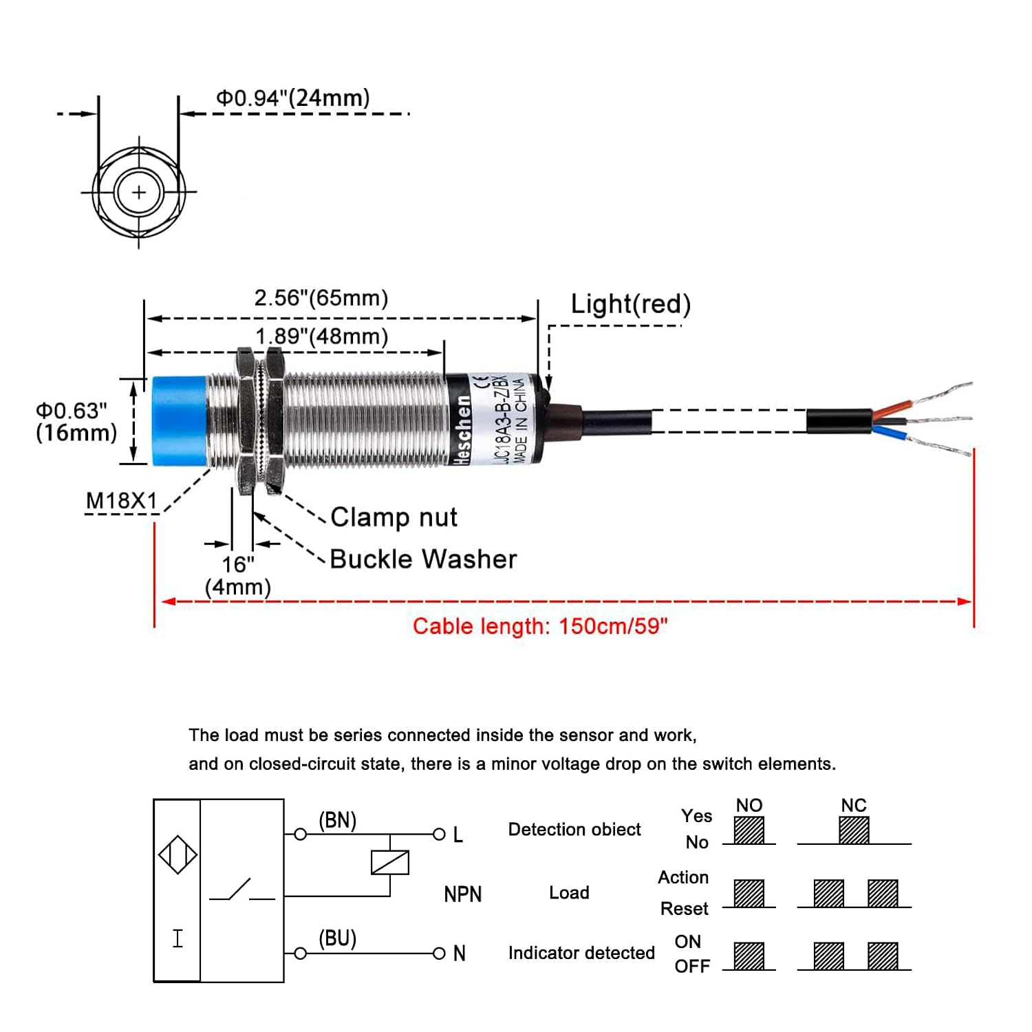
Heschen NO
$8.99
In stock on Amazon
Check price on AmazonM30: Greater Range, Greater Bulk
M30-body sensors publish nominal sensing ranges of 15–20 mm to a standard metallic target. Through a 5 mm HDPE wall the effective range is roughly 8–15 mm—meaningfully more headroom than M18 allows. The Balluff BCS Series Technical Manual formalizes this as a derating factor: effective sensing range through a non-metallic wall is typically 50–70% of the rated nominal range (Sn) to a grounded metal plate, depending on target permittivity. An M30 rated at 15 mm Sn may reliably trip at 9–10 mm through wall; an M18 rated at 10 mm Sn may only reach 6–7 mm under the same conditions.
That through-wall performance gap is the dominant reason to specify M30 over M18 in liquid level applications. If your tank wall is 8 mm thick and you’re detecting water, an M18 may not reliably trip after the dielectric reduction penalty is applied. An M30 gives you working margin.
The tradeoff is body bulk. M30 requires a 30 mm threaded mounting hole and a lock-nut footprint that may not fit tight panel spaces, small conduit boxes, or narrow hopper walls. On thin-wall polycarbonate tanks, the larger bore risks stress-cracking the plastic around the mounting hole—a concern absent with M18.
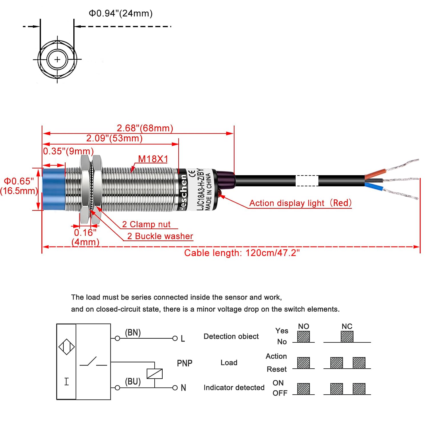
Heschen
$9.29
In stock on Amazon
Check price on AmazonWhen to Step Beyond M30
For wall thicknesses or medium gaps above 15 mm, capacitive proximity sensing reaches its reliable limit. At that range, consider ultrasonic level sensors or guided-wave radar. Control Engineering (“Proximity Sensor Output Types: NPN, PNP, and AC Wiring Considerations”) notes this boundary in its sensor-selection overview: capacitive sensing is the correct technology for short-range non-contact level detection, but ultrasonic and radar technologies take over as gap distance increases. Both technologies are available with the same PLC-compatible 24VDC discrete or analog outputs described below, so the output-selection logic still applies.
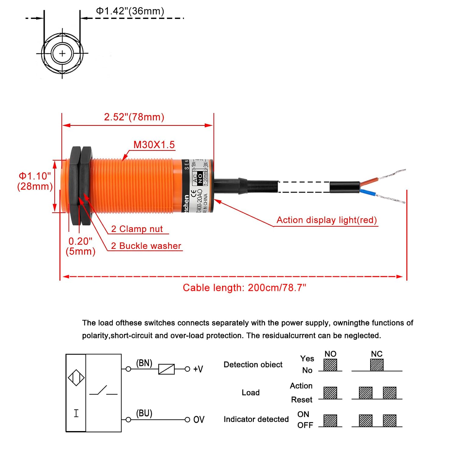
Heschen NO
$18.49
In stock on Amazon
Check price on AmazonBody Size Comparison Summary
| Body Size | Nominal Sn (metal target) | Practical Range Through 5 mm HDPE | Best Fit |
|---|---|---|---|
| M12 | 4–6 mm | 2–4 mm | Thin-wall labels, packaging |
| M18 | 8–12 mm | 5–8 mm Heschen NO — $8.99 | Walls under 6 mm, tight geometry |
| M30 | 15–20 mm | 8–15 mm Heschen — $9.29 | Walls 6–15 mm, liquid level through plastic tanks |
Ranges derived from Keyence Capacitive Sensor Principles and Selection Guide, Omron E2K Series Datasheet, and Banner Engineering Capacitive Sensor Product Family Overview. Actual range varies with target dielectric constant and flush vs. non-flush mounting.
AC vs. DC Output: A Wiring Architecture Decision, Not a Performance Decision
Capacitive sensors are sold in two fundamental output configurations: AC-output models (typically 2-wire, line-voltage, wired directly into a 120VAC or 240VAC control circuit or relay) and DC-output models (3-wire or 4-wire, 10–30VDC, with NPN or PNP transistor outputs). Choosing wrong here does not affect sensing performance—it means an incompatible interface with your controller or relay logic, which is its own kind of failure.
AC Output (2-Wire, Line Voltage)
AC-output capacitive sensors are the simple, legacy choice. Two wires, no polarity, line voltage passes through the sensor like a solid-state relay. They are specified heavily in retrofits to older relay-logic panels, direct pump-control circuits, and any installation where a PLC is not involved and the installer wants to wire directly to a motor starter or contactor coil.
The practical penalty is leakage current. AC-output solid-state sensors pass a small residual current—typically 0.8–2 mA—even in the OFF state to power their internal electronics. As Control Engineering documents in its proximity sensor output types overview, this leakage can hold in sensitive relay coils rated below 3–5 mA, causing false ON states. You need to verify your relay’s minimum dropout current against the sensor’s maximum leakage before specifying. Most modern relays handle this; older DIN-rail relay modules sometimes do not.
AC sensors also provide no direct PLC interface without a relay or coupler. If your architecture is a 24VDC PLC I/O card, an AC sensor requires an intermediate relay or solid-state relay to interface—adding hardware, cost, and a potential failure point.
DC Output (3-Wire NPN or PNP, 24VDC)
DC output is the dominant specification for new installations. A 3-wire DC sensor draws supply voltage on one wire, provides a common reference on a second, and switches its output on the third wire. Most modern PLCs—including Siemens S7 series, Allen-Bradley Micro820 and CompactLogix, and Omron CP1H—accept 24VDC discrete inputs natively, making this a direct connection with no intermediate relay required.
NPN vs. PNP is the sub-choice within DC:
- NPN (sinking) switches the output wire to ground (negative common). Used with PLC sinking input cards. Common in Asian-market PLC configurations and many Omron installations.
- PNP (sourcing) switches the output wire to the supply positive. Used with sourcing input cards. Dominant in European and most North American automation environments. Banner Engineering’s Capacitive Sensor Product Family Overview notes that North American SKUs default to PNP sourcing output.
The NPN vs. PNP decision is entirely driven by your PLC input card type—not sensor performance. Pull the I/O card specification sheet before ordering. A PNP sensor on a sinking-only input card will not function.
Calibration and Installation Practices That Determine Whether the Spec Sheet Matches Reality
Even a correctly specified sensor fails in the application when installed carelessly. Three practices account for most of the gap between published performance and field behavior.
1. Sensitivity adjustment at actual operating conditions. Always set sensitivity with the target at the threshold position—not at maximum sensitivity, not at zero. For level detection through a tank wall, commission with the tank at the trip level and back off the sensitivity potentiometer until the sensor just fires reliably. The Keyence Capacitive Sensor Principles and Selection Guide recommends maintaining a 20% margin between the set point and maximum sensitivity to account for temperature drift and surface contamination over time.
2. Temperature derating. Capacitive sensors are more temperature-sensitive than inductive sensors. The dielectric constants of many materials change with temperature—water’s permittivity decreases as temperature rises, which reduces effective sensing range. Sensors Magazine (“Selecting Capacitive Sensors for Difficult Level Detection Applications”) specifically flags this for outdoor storage tanks in climates with wide seasonal temperature swings. Verify that your target material’s dielectric constant is stable across the sensor’s rated operating temperature range before finalizing the spec.
3. Mounting clearance for shielded vs. unshielded sensors. Unshielded (non-flush) sensors have longer sensing ranges but are susceptible to interference from adjacent metal mounting structures. Mounting an unshielded M30 in a steel bracket without adequate lateral clearance causes the bracket itself to load the sensing field, reducing effective range below what a flush-mounted installation would achieve. The Balluff BCS Series Technical Manual includes specific mounting clearance guidelines for both shielded and unshielded configurations; deviating from those clearances is among the most common installation errors documented in their technical support records.
The If/Then Decision Map
Before placing your order, run through this sequence:
-
What is your target medium? Water or oils through a plastic tank wall → M30 flush-mount for sealing integrity, DC PNP output to PLC. Bulk solids in a plastic hopper → M30 non-flush for maximum range, DC output. Labels or packages in presence-detection → M18 flush, DC output.
-
What is your wall or gap distance? Under 6 mm → M18 is sufficient. 6–15 mm → M30. Over 15 mm → evaluate ultrasonic or guided-wave radar as described above.
-
What is your controller interface? 24VDC PLC with sinking inputs → NPN DC. 24VDC PLC with sourcing inputs or unspecified → PNP DC. No PLC, direct relay or contactor → AC 2-wire, with leakage-current verification against your relay’s dropout spec.
-
What is your environment? Food or beverage with washdown requirements → specify IP67 or IP69K rated housing and stainless-steel hardware. Chemical exposure → verify housing material (PTFE or PVDF sensor face vs. standard ABS). High ambient temperature → confirm rated operating range against actual enclosure temperature with temperature-derating margin.
Standard DC PNP variants in M18 and M30 from established manufacturers—Keyence, Omron, Banner Engineering, Balluff, and Sick—are stocked through major distributors with lead times typically under two weeks for non-specialty models. Pricing for M18 DC variants runs approximately $35–$90 at distribution; M30 DC variants run $55–$140, with shielded and specialty-housing configurations at the high end. AC variants in both sizes typically run 15–25% below the equivalent DC price point.
The selection decision is faster than it looks on the spec sheet once the application geometry and controller type are locked. The traps are in through-wall dielectric derating, sensitivity margin, and output wiring compatibility—all solvable at the design stage if you ask the right questions before the panel is built.